Cooler applicable to wind generating set

A technology for wind turbines and coolers, applied in wind turbines, wind power generation, engines, etc., can solve the problems of waste of production labor, loss of imported wind flow, clogging of filters, etc. blocking effect

Inactive Publication Date: 2019-11-15
HOHAI UNIV
View PDF11 Cites 3 Cited by
  • Summary
  • Abstract
  • Description
  • Claims
  • Application Information

AI Technical Summary

Problems solved by technology

Manual maintenance and cleaning, because the air inlets of many unit coolers are outside the engine room, there are many safety factors, and at the same time, it needs to waste production labor; the filter screen also has the problem of clogging, which needs to be cleaned and replaced regularly, which further causes waste of resources. will cause loss of inlet air flow

Method used


Image

  • Cooler applicable to wind generating set
  • Cooler applicable to wind generating set
  • Cooler applicable to wind generating set

Examples


Embodiment 1

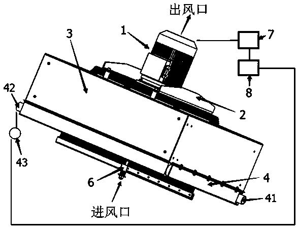
[0032] A cooler suitable for wind power generating sets, which is controlled by a motor 1, a forward and reverse control module 7, a motor bracket 2, a cover body 3, a cooling core 4, fan blades 5, a cleaning device 6, a temperature sensor 43, and a PLC Device 8 is composed.

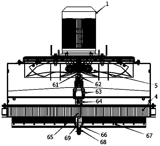
[0033] The cooling core 4 is placed at the front end of the motor 1 (shaft), the output end of the motor shaft is fixedly connected to the first transmission shaft 61 , and the fan blade 5 is fixedly connected to the first transmission shaft 61 . The output end of the first transmission shaft 61 is connected to the speed reducer 63 through the clutch 62 in turn, and then the second transmission shaft 65 is linked through the coupling 64; the second transmission shaft 65 passes through the reserved round hole at the center of the cooling core 4, Rotate cleaning device 6.

[0034] The cleaning device 6 is made up of a hair brush 67 , a hair brush skeleton 66 and a progressive device 68 . The hairbrush 67...

Embodiment 2

[0043] Based on the structure of Embodiment 1, a temperature sensor 43 is provided at the liquid outlet 42 of the coolant, and is connected to the PLC controller 8; the PLC controller 8 controls forward rotation and reverse rotation of the motor 1 according to the feedback of the temperature sensor 43 .

[0044] When the temperature of the liquid outlet 42 increases, the cooling effect decreases, and the surface of the cooling core 4 is blocked, and the temperature sensor 43 transmits a signal to the PLC controller 8 through the data line, and the PLC controller 8 controls the motor 1 to stop normal operation (positive Turn), enter the reverse cleaning state, and the cleaning time can be set according to the particulate matter environment in the air of each area. After the cleaning is finished, the PLC controller 8 controls the motor 1 to work normally (forward rotation), and at the same time the clutch 62 disengages from the engagement with the reducer 63, and the cleaning dev...


PUM


Abstract

The invention discloses a cooler applicable to a wind generating set. A fan is fixedly connected onto a motor shaft; a cooling core is arranged at the front end of the fan; a hairbrush is arranged onthe outer side face and / or the inner side face of the cooling core and is fixed on a hairbrush framework; a second transmission shaft for rotating the hairbrush framework is linked with the motor shaft through a clutch; a motor is driven by a PLC; when the motor rotates forward, the clutch is in the separating state; and when the motor rotates reversely, the clutch is in the closing state. The PLCcontrols forward and reverse rotation of the motor; when the motor rotates forward, the fan sucks cooling air passing through the cooling core; when the motor rotates reversely, the motor is linked with a cleaning device through the clutch, and the fan rotating reversely enhances the cleaning effect; a temperature sensor is adopted to detecting the temperature of coolant to feed the temperature back to the PLC, the PLC controls forward and reverse rotation of the motor to realize automatic operation and automatic cleaning operation of the cleaning device, so that the cooler plugging problem is effectively solved; and the cooler has high practicality and wide applicability.

Description

technical field [0001] The invention relates to a cooler, in particular to a cooler suitable for wind power generating sets, and belongs to the technical field of wind power generation industry. Background technique [0002] There are many heat-generating equipment during the operation of wind turbines, mainly including gearboxes, generators and frequency converters. [0003] At present, large-scale MW-level wind turbines generally dissipate the heat generated by gearboxes, generators, and frequency conversion cabinets by installing oil cooling and water coolers. [0004] The cooling effect of the cooler is mainly affected by the air flow inhaled by the cooling fan, but in the actual operation process, the dust particles and flocs in the air will be adsorbed on the surface of the air inlet of the cooling core, causing the air circulation to be blocked, which in turn will cause the wind turbine generator Overheating protection, reducing power or stopping power generation wil...

Claims


Application Information

Patent Timeline
Patent Type & Authority Applications(China)
IPC IPC(8): F03D80/60F28G1/02F28G1/16
CPCF03D80/60F28G1/02F28G1/163Y02E10/72
Inventor 汪亚洲蔡新郭兴文许波峰
Owner HOHAI UNIV
Why Eureka
Try Eureka