Fluid valve for biomass processing system

A biomass treatment and fluid technology, applied in the direction of multi-way valves, valve devices, engine components, etc., can solve the problems of high purchase cost, dust deposition, etc., and achieve the effect of low manufacturing cost and low manufacturing difficulty

Pending Publication Date: 2019-11-15
四川赫菲斯托气化发电设备有限公司
View PDF0 Cites 1 Cited by
  • Summary
  • Abstract
  • Description
  • Claims
  • Application Information

AI Technical Summary

Problems solved by technology

[0006] In the prior art, the corresponding valves adopt three-way valves, globe valves, gate valves, etc. to achieve the desired purpose, but these existing valves have high purchase costs and are prone to dust deposition during use

Method used


Image

  • Fluid valve for biomass processing system
  • Fluid valve for biomass processing system

Examples


Embodiment 1

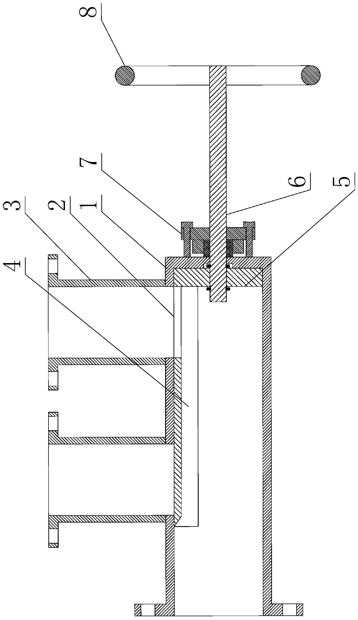
[0037] Such as figure 1 and figure 2 As shown, the fluid valve used in the biomass treatment system includes a valve body and a valve plate 4 installed in the valve body. The valve body includes a dead leg section 1 and two outlet pipes 3. The inlet ends of the outlet pipes 3 are both Connected on the side of the dead-leg section 1, and in the circumferential direction of the dead-leg section 1, the two outlet pipes 3 are connected at the same position in the circumferential direction;

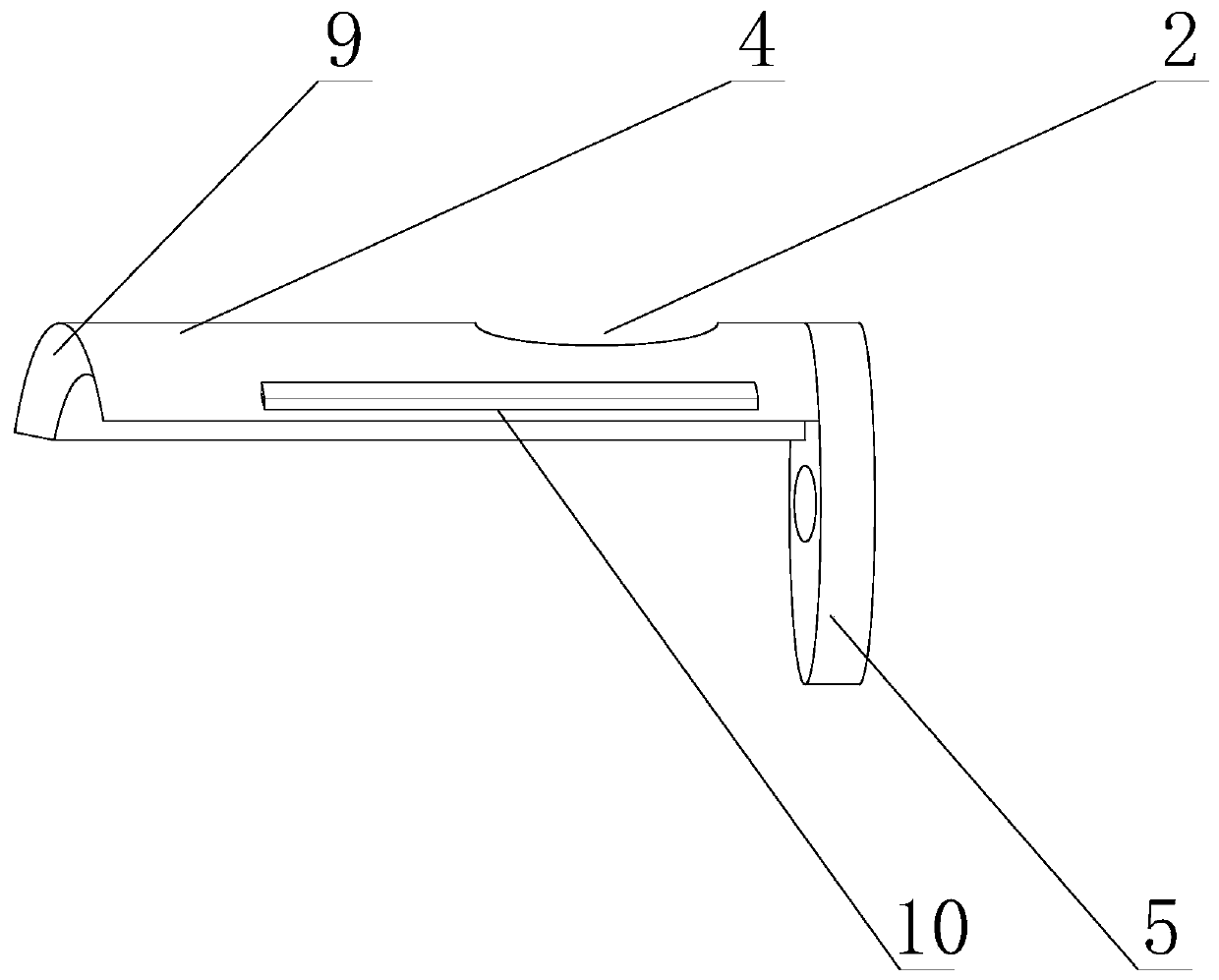
[0038] The valve plate 4 is in the shape of an arc plate, and the valve plate 4 is installed in the dead-leg section 1, and the protruding side of the valve plate 4 is attached to the inner surface of the dead-leg section 1;

[0039] The end of the valve plate 4 close to the sealing end of the dead-leg section 1 is also fixedly connected with a slide plate 5, and the slide plate 5 is used as a sealing plate for cutting off the dead-leg section 1;

[0040] It also includes a communication ho...

Embodiment 2

[0046] The present embodiment is further limited on the basis of embodiment 1, as figure 1 and figure 2 As shown, as a driving mechanism implementation scheme with simple structure, the driving mechanism includes a threaded rod 6 and a hand wheel 8, the axis of the threaded rod 6 is collinear with the axis of the blind pipe section 1, and the threaded rod 6 is screwed to the blind pipe section 1. On the sealed end of pipe section 1;

[0047] One end of the threaded rod 6 is located inside the dead-leg section 1, and the other end of the threaded rod 6 is positioned at the outside of the dead-leg section 1. The slide plate 5 is rotatably connected to one end of the threaded rod 6 extending into the dead-leg section 1, and the hand wheel 8 is connected to the threaded rod. 6. One end located outside the blind leg section 1 is fixedly connected. In this solution, by using the handwheel 8 to rotate the threaded rod 6, the direction of rotation of the threaded rod 6 is adjusted ...


PUM


Abstract

The invention discloses a fluid valve for a biomass processing system. The fluid valve for the biomass processing system comprises a valve body and a valve plate, wherein the valve body comprises a blind pipe section and two outlet pipes; the valve plate is in an arc plate shape, the valve plate is installed in the blind pipe section, and the convex side of the valve plate is attached to the innersurface of the blind pipe section; a sliding plate is fixedly connected to one end, close to the sealing end of the blind pipe section, of the valve plate, and serves as a sealing plate for cutting off the blind pipe section; the valve plate further comprises a communication hole arranged on the valve plate, the communication hole penetrates through the concave side and the convex side of the valve plate, and the edge of the communication hole is connected with the sliding plate; and a drive mechanism is also included. The fluid valve is simple in structure and low in processing and manufacturing cost, and dust can be effectively prevented from being deposited in the valve.

Description

technical field [0001] The invention relates to the technical field of valves, in particular to a fluid valve used in a biomass treatment system. Background technique [0002] With the rapid development of my country's social economy, the acceleration of urbanization and the rapid improvement of people's living standards, the garbage and waste generated in the process of urban production and life have also increased rapidly, and the situation of domestic garbage occupying land and polluting the environment has become more and more obvious. The massive increase of household garbage makes garbage disposal more and more difficult. In addition, a large amount of straw obtained in agricultural production, and a large amount of branches and sawdust obtained in wood production, one of the traditional methods is to use direct incineration to obtain heat for reuse, and the resulting environmental pollution and other problems have gradually caused social problems widespread attention....

Claims


Application Information

Patent Timeline
Patent Type & Authority Applications(China)
IPC IPC(8): F16K11/07
CPCF16K11/07
Inventor 彭罡彭琪
Owner 四川赫菲斯托气化发电设备有限公司
Why Eureka
Try Eureka