Thermoelectric supercooling cross-critical CO2 heat pump combined heating system

A heating system and transcritical technology, applied in the field of heat pumps, can solve the problems of low energy efficiency, achieve the effects of improving service life, reducing CO2 operating high pressure, and reducing pressure ratio

Pending Publication Date: 2019-11-15
TIANJIN UNIV OF COMMERCE
View PDF0 Cites 7 Cited by
  • Summary
  • Abstract
  • Description
  • Claims
  • Application Information

AI Technical Summary

Problems solved by technology

So CO 2 Heat pumps are suitable for systems with large temperature differences between supply and return water (such as heat pump water heater systems), such as using CO 2 Heat pumps are used for heating and are less energy efficient

Method used


Image

  • Thermoelectric supercooling cross-critical CO2 heat pump combined heating system
  • Thermoelectric supercooling cross-critical CO2 heat pump combined heating system
  • Thermoelectric supercooling cross-critical CO2 heat pump combined heating system

Examples


Embodiment 1

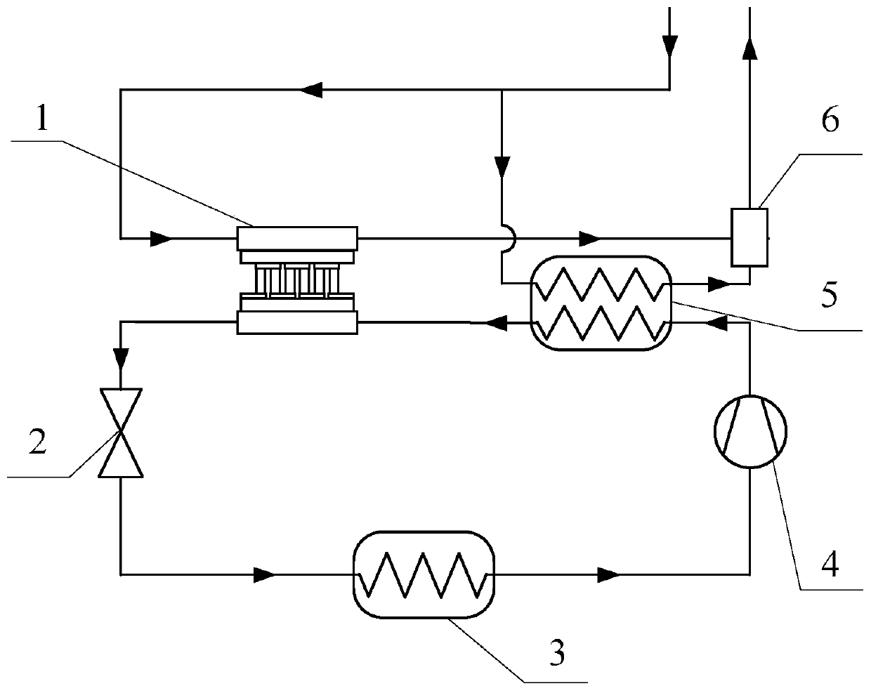
[0025] Example 1: Single-stage thermoelectric subcooled transcritical CO 2 Combined heating system with heat pump

[0026] The present invention thermoelectric subcooled transcritical CO 2 Heat pump combined heating system consists of thermoelectric subcooler and transcritical CO 2 Composition of heat pump cycle, single-stage thermoelectric subcooled transcritical CO 2 Schematic diagram of heat pump combined heating system figure 1 As shown, the single-stage thermoelectric subcooled transcritical CO 2 Heat pump combined heating system cycle T-s diagram Figure 4 shown. Among them, the dotted line is the transcritical CO 2 Heat pump cycle (1-2-3-4), the thin solid line is the thermoelectric subcooling process, and the temperature of the cold end of the thermoelectric subcooler is Figure 4 The indicated a-b corresponds to the temperature, and the temperature at the hot end of the thermoelectric subcooler is Figure 4 The shown c-d correspond to the temperature, and the ...

Embodiment 2

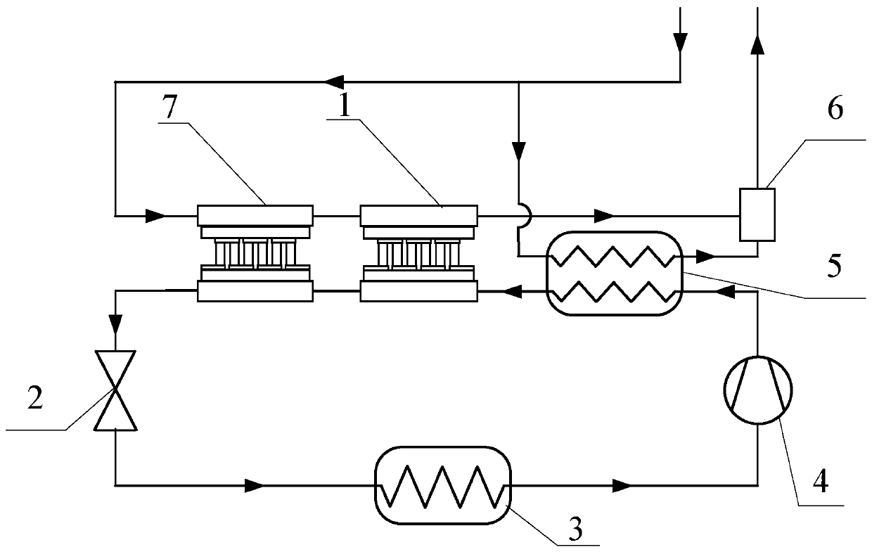
[0029] Example 2: Two-stage thermoelectric subcooled transcritical CO 2 Combined heating system with heat pump

[0030] The present invention thermoelectric subcooled transcritical CO 2 Heat pump combined heating system consists of thermoelectric subcooler and transcritical CO 2 Composition of heat pump cycle, two-stage thermoelectric subcooled transcritical CO 2 Schematic diagram of heat pump combined heating system figure 2 As shown, the two-stage thermoelectric subcooled transcritical CO 2 Heat pump combined heating system cycle T-s diagram Figure 5 shown. Among them, the dotted line is the transcritical CO 2 Heat pump cycle (1-2-3-4), the thin solid line is the thermoelectric subcooling process, and the cold end temperatures of the two-stage thermoelectric subcoolers are Figure 5 Shown a 1 -b 1 、a 2 -b 2 Corresponding to the temperature, the temperature at the hot end of the two-stage thermoelectric subcooler is Figure 5 shown c 1 -d 1 、c 2 -d 2 Corresp...

Embodiment 3

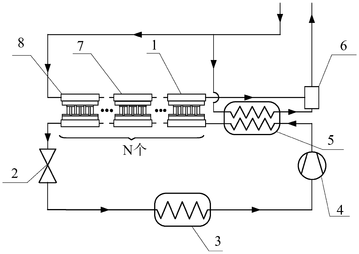
[0033] Example 3: Multi-stage thermoelectric subcooled transcritical CO 2 Combined heating system with heat pump

[0034] The present invention thermoelectric subcooled transcritical CO 2 Heat pump combined heating system consists of thermoelectric subcooler and transcritical CO 2 Composition of heat pump cycle, multi-stage thermoelectric subcooling transcritical CO 2 Schematic diagram of heat pump combined heating system image 3 As shown, the multistage thermoelectric subcooled transcritical CO 2 Heat pump combined heating system cycle T-s diagram Figure 6 shown. Among them, the dotted line is the transcritical CO 2 Heat pump cycle (1-2-3-4), the thin solid line is the thermoelectric subcooling process, and the cold end temperatures of the multi-stage thermoelectric subcoolers are Figure 6 Shown a 1 -b 1 、a 2 -b 2 …a i -b i …a n -b n Corresponding to the temperature, the temperature at the hot end of the multi-stage thermoelectric subcooler is Figure 5 sho...


PUM


Abstract

The invention discloses a thermoelectric supercooling cross-critical CO2 heat pump combined heating system. An outlet of an evaporator is connected with an inlet of a compressor; an outlet of the compressor is connected with an inlet of the working medium side of a gas cooler; an outlet of the working medium side of the gas cooler is connected with an inlet of the cold end of a thermoelectric supercooling device; an outlet of the cold end of the thermoelectric supercooling device is connected with an inlet of a throttling valve; an outlet of the throttling valve is connected with an inlet of the evaporator; a heating water return outlet is connected with an inlet of the thermal end of the thermoelectric supercooling device; an outlet of the thermal end of the thermoelectric supercooling device is connected with an inlet of the heat exchange fluid side of the gas cooler; an outlet of the heat exchange fluid side of the gas cooler is connected with an inlet of a mixing tank; and an outlet of the mixing tank is connected with a heating water return inlet. According to the system, the throttling loss is reduced to a greater extent, the high pressure of CO2 operation is further reduced,the overall system efficiency of a CO2 heat pump is improved, the compression ratio of the compressor is reduced, the isentropic efficiency is improved, and the service life of the compressor is prolonged.

Description

technical field [0001] The invention relates to the technical field of heat pumps, in particular to a thermoelectric subcooled transcritical CO 2 Heat pump combined heating system. Background technique [0002] As a basic industry with overall and leading influence on the development of the national economy, the heating industry is closely related to people's lives. Most towns and rural areas in northern my country rely on coal for heating, and it is still low-quality coal, which produces more pollutants and is more harmful to the environment. [0003] In order to control the smog problem in northern winter, the government proposed to use coal to electricity and other measures to solve the northern winter heating, that is, to replace the traditional coal-fired heating with electricity, gas and other cleaner energy sources. For the heating method of direct electric heating (electric boiler, electric heater, heating cable, etc.), the energy is directly converted from high-gr...

Claims


Application Information

Patent Timeline
Patent Type & Authority Applications(China)
IPC IPC(8): F24D3/18F25B9/00F25B30/02F25B40/02
CPCF24D3/18F25B9/008F25B30/02F25B40/02
Inventor 代宝民张鹏赵晓璇漆乐杨茜茹姜文玲齐海峰
Owner TIANJIN UNIV OF COMMERCE
Why Eureka
Try Eureka