Laser radar system and target object recognition method

A technology of laser radar and laser light source, which is applied in the field of laser measurement, can solve the problems of difficult implementation and high requirements for laser light source control, and achieve the effect of improving anti-interference ability

Pending Publication Date: 2019-11-15
HESAI TECH CO LTD
View PDF5 Cites 7 Cited by
  • Summary
  • Abstract
  • Description
  • Claims
  • Application Information

AI Technical Summary

Problems solved by technology

However, due to the need to encode multiple pulses on a time scale of nanoseconds, the c

Method used


Image

  • Laser radar system and target object recognition method
  • Laser radar system and target object recognition method
  • Laser radar system and target object recognition method

Examples


Example Embodiment

[0026] The technical problem solved by this application is to provide a laser radar system and a target object recognition method, which realizes the encoding and detection of laser beams of different wavelengths emitted by multiple laser light sources, which not only improves the anti-interference ability of the laser radar system , and reduces the difficulty of design, and is easy to implement and popularize in engineering.

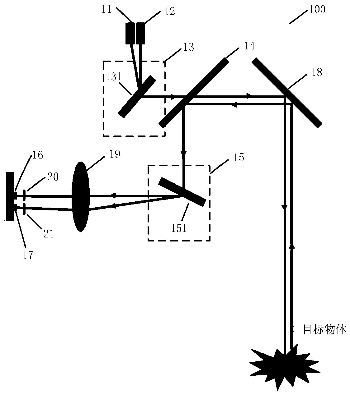
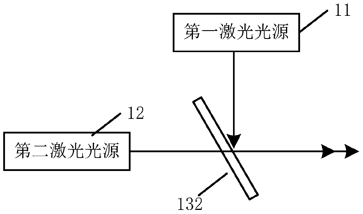
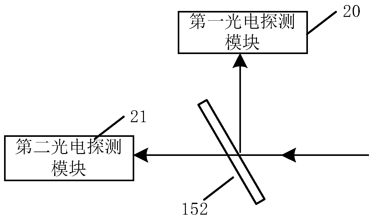
[0027] see figure 1 As shown, the embodiment of the present application provides a laser radar system 100, including: a first laser light source 11, a second laser light source 12, an optical common path device 13, a light splitting device 14, an optical branching device 15, a first photodetector Module 16 , second photodetection module 17 , scanning device 18 and converging lens 19 .

[0028]The first laser light source 11 and the second laser light source 12 are used to respectively emit laser beams of different wavelengths. For example, the first l...


PUM


Abstract

The invention provides a laser radar system and a target object recognition method. The laser radar system comprises multiple laser light sources, a light sharing device, a light splitting device, a scanning device, a light branching device, a converging lens and multiple photoelectric detection modules, wherein the multiple laser light sources output laser beams with different wavelengths, and encoding is realized according to difference of optical parameters and/or transmission characteristics. Meanwhile, the multiple photoelectric detection modules receive echo beams with different wavelengths respectively, so that whether a target object is valid or not can be determined according to optical parameters and/or transmission characteristics of the echo beams with different wavelengths. Therefore, the laser beams emitted by the multiple laser light sources are encoded and detected respectively by the laser radar system provided by the embodiment of the invention, anti-jamming capability of the laser radar system is improved, and furthermore, compared with a method for encoding different sequences produced by the same laser light source, the method has the advantages of reducing design difficulty and facilitating implementation and popularization in engineering.

Description

technical field [0001] The present application relates to the technical field of laser measurement, in particular to a laser radar system and a method for identifying a target object. Background technique [0002] The lidar system is a scanning sensor using laser ranging technology. Its working principle is similar to that of a general radar system. It detects targets by emitting laser beams, and forms point clouds and acquires data by collecting reflected beams. Lidar systems have been widely used in automotive autonomous driving, unmanned driving, positioning and navigation, space mapping, robotics and other fields. [0003] Current lidar systems usually use the time-of-flight method for ranging, that is, the distance to the target object is calculated based on the time it takes for the echo beam to be received after the laser beam is emitted. However, since the received echo beam may be interfered by other laser beams emitted by the laser radar, or even by laser beams wi...

Claims


Application Information

Patent Timeline
IPC IPC(8): G01S7/481
CPCG01S7/4811G01S7/4817
Inventor 卢炎聪向少卿
Owner HESAI TECH CO LTD
Why Eureka
Try Eureka