Material information mapping method for material point method for large deformation response of structure
An information mapping and material point technology, which is applied in the material information mapping field of the material point method, achieves the effect of overcoming the shortcomings of complex interpolation algorithms, avoiding the complexity of solving algorithms, and avoiding the non-conservation of mass and momentum
- Summary
- Abstract
- Description
- Claims
- Application Information
AI Technical Summary
Problems solved by technology
Method used
Image
Examples
Embodiment 1
[0025] A material information mapping method for the material point method of the large deformation response of the structure, comprising the following steps:
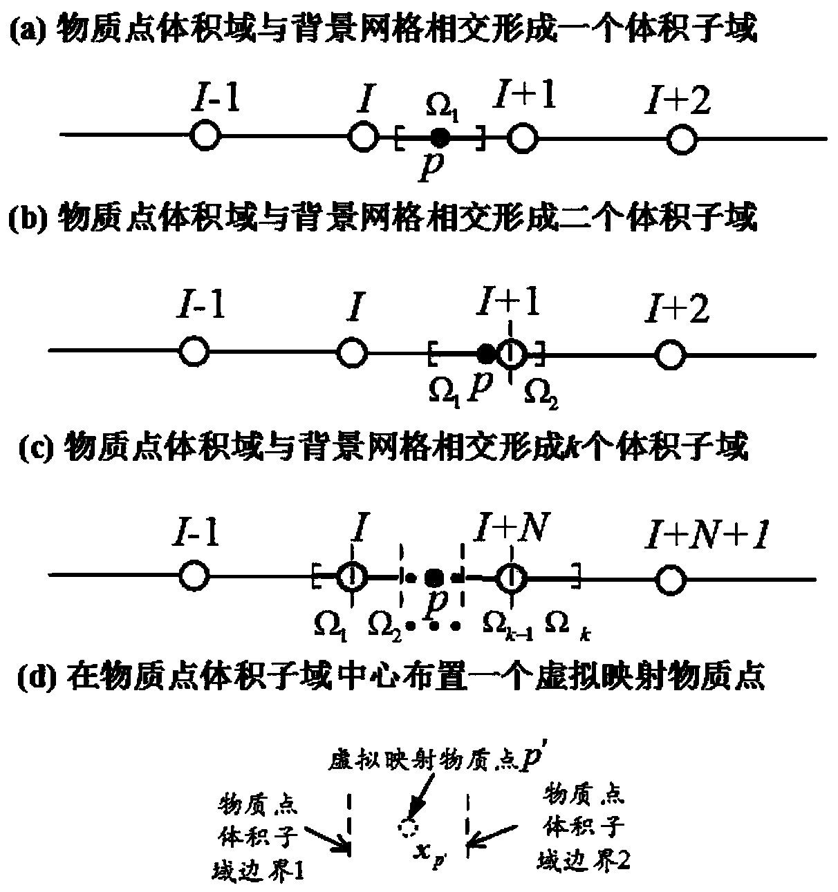
[0026] Step 1. Based on the discrete problem domain of Lagrangian material points, initialize the material information of each material point such as mass, momentum, density, stress-strain, and deformation gradient; at the same time, arrange a set of regular Euler-type background grids to realize The solution of the governing equation and the interaction and connection between each material point;
[0027] Step 2. Determine the current volume domain of each material point through the deformation gradient of the material point;
[0028] At time t, the volume domain of material point p can be expressed as:
[0029]
[0030] in: is the deformation gradient of material point p at time t; and Respectively represent the volume domain of the material point p at the initial time and time t.
[0031] Step 3. Determin...
Embodiment 2
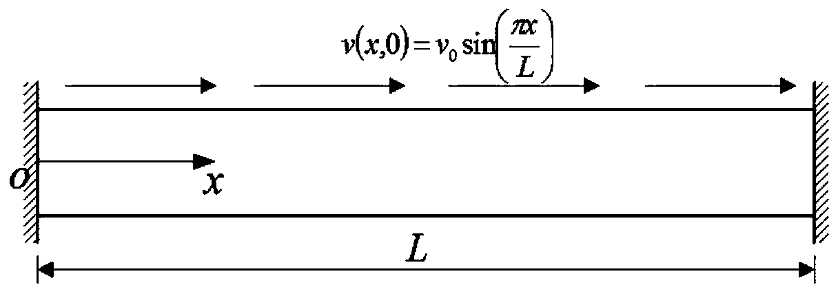
[0076] This embodiment takes a one-dimensional rod as an example to specifically illustrate the application of the method of the present invention;
[0077] Such as image 3 As shown, a one-dimensional rod with initial velocity and fixed at both ends will produce a dynamic response along the axial direction due to the effect of the initial velocity. Utilize the material point method and the present invention to analyze the vibration response of this one-dimensional rod respectively, and the calculation parameters are selected as follows: modulus of elasticity E=50Pa, density ρ=25kg / m 3 , model length L=1m, v 0 =0.1m / s, the grid size is 6.25mm, 4 material points are arranged in each background grid, and the time step is 0.5μs. Figure 4 The distribution of displacement and stress along the rod axis and the corresponding L 2 error.
Embodiment 3
[0079] This embodiment takes a two-dimensional free beam as an example to specifically illustrate the application of the method of the present invention;
[0080] Such as Figure 5 As shown, a straight beam with constant section with length L=0.06m and height H=0.01m, where point a is the center point of the beam, the elastic modulus of the beam is E=318GPa, density ρ=1845kg / m3, Poisson’s ratio v= 0.054. At the initial moment t=0, each point in the beam is distributed with a first-order free beam bending vibration modal velocity; when t>0, the beam vibrates in a free state, respectively using the material point method and the present invention for this two-dimensional free beam The vibration response is simulated, where the background grid size is dx=dy=6.25×10 -4 m, time step dt=0.001 μs, and 4×4 material points are arranged in each grid. Figure 6 The normal stress contour of the beam in the x direction calculated by the material point method and the present invention is ...
PUM
| Property | Measurement | Unit |
|---|---|---|
| Elastic modulus | aaaaa | aaaaa |
| Density | aaaaa | aaaaa |
| Elastic modulus | aaaaa | aaaaa |
Abstract
Description
Claims
Application Information
 - R&D
- Intellectual Property
- Life Sciences
- Materials
- Tech Scout
- Unparalleled Data Quality
- Higher Quality Content
- 60% Fewer Hallucinations
Browse by: Latest US Patents, China's latest patents, Technical Efficacy Thesaurus, Application Domain, Technology Topic, Popular Technical Reports.
© 2025 PatSnap. All rights reserved.Legal|Privacy policy|Modern Slavery Act Transparency Statement|Sitemap|About US| Contact US: help@patsnap.com


