
Diesel engine fault diagnosis method based on tensor Tucker decomposition fuzzy control

A fuzzy control and fault diagnosis system technology, applied in the direction of reasoning methods, measuring devices, computer components, etc., can solve problems such as economic loss, signal mutual interference, large nonlinear and complex coupling, casualties, etc., to improve accuracy, Reduce external interference and mutual interference between signals, and solve the effect of one cause and multiple effects

Inactive Publication Date: 2019-11-15
NORTHWEST A & F UNIV
View PDF0 Cites 9 Cited by
  • Summary
  • Abstract
  • Description
  • Claims
  • Application Information

AI Technical Summary

Problems solved by technology

[0002] The normal operation of the diesel engine can be described as an important guarantee for the safe operation of the equipment. However, there are many types of diesel engine failures, and there are many reasons for the failures, that is, the diesel engine failures have the characteristics of "one effect and multiple causes" and "one cause and multiple effects". Failure of a certain part will often lead to poor working condition of the engine, which will affect the normal operation of the equipment, which may cause economic losses and even casualties
[0003] The diesel engine fault diagnosis method has gradually evolved from the traditional experience method and observation method to a conventional diagnosis technology method based on dynamic testing technology and signal processing technology as the core. However, in the existing signal feature extraction methods, the signal to be processed often appears as a one-dimensional signal in the time domain or frequency domain, that is, a vector, but in fact the various signals of the engine are not independent of each other , many signals interfere with each other and have strong nonlinear and complex coupling characteristics. In addition, due to the characteristics of "one effect, multiple causes" and "one cause, multiple effects" of diesel engine faults, the conventional fault diagnosis system inaccurate diagnosis

Method used


Image

  • Diesel engine fault diagnosis method based on tensor Tucker decomposition fuzzy control
  • Diesel engine fault diagnosis method based on tensor Tucker decomposition fuzzy control
  • Diesel engine fault diagnosis method based on tensor Tucker decomposition fuzzy control

Examples


Embodiment Construction

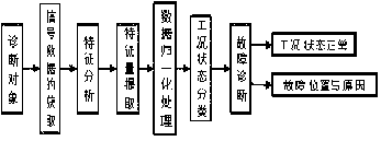
[0018] The specific implementation of the diesel engine fault diagnosis method based on tensor Tucker decomposition fuzzy control is as follows.

[0019] The step 1 of collecting data signals from sensors in the ECU includes: an air flow meter, a coolant temperature sensor, an intake manifold pressure sensor, a regulating piston movement sensor, an engine speed sensor, and the like.

[0020] The second step is to construct a third-order tensor composed of signal category, rotational speed and crank angle according to the above sensor signals , the signal category is signals other than the crankshaft position sensor and vehicle speed sensor, the speed is the signal of the engine sensor, and the crankshaft angle is the signal of the crankshaft position sensor.

[0021] The Tucker decomposition is a high-order principal component analysis, which represents a tensor as a core (core) tensor multiplied by a matrix along each mode, assuming that the column vectors of the decomposed ...


PUM


Abstract

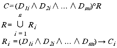
The invention provides an engine fault diagnosis method based on tensor tucker decomposition fuzzy control. Data in an existing diesel engine ECU are integrated to form third order tensioners; a tensor tucker decomposition thought is utilized, feature extraction is carried out by using Tucker decomposition of a tensor of HOSVD-ALS to obtain a core tensor and a horizontal slice matrix Bm thereof; and data normalization processing is performed on the data of the core tensor horizontal slice matrix Bm, reasoning operation is performedon the two processed tensors by adopting a fuzzy method to obtain an output quantity matrix, and defuzzification is performed on the output quantity matrix to obtain an accurate output quantity matrix, thereby realizing fault diagnosis on short circuit, open circuit and failure of the diesel engine sensor.

Description

technical field [0001] The invention belongs to the field of diesel engine fault diagnosis, and in particular relates to a diesel engine fault diagnosis method. Background technique [0002] The normal operation of the diesel engine can be described as an important guarantee for the safe operation of the equipment. However, there are many types of diesel engine failures, and there are many reasons for the failures, that is, the diesel engine failures have the characteristics of "one effect and multiple causes" and "one cause and multiple effects". Failure of a certain part will often lead to poor working condition of the engine, which will affect the normal operation of the equipment, and may cause economic losses and even casualties. [0003] The diesel engine fault diagnosis method has gradually evolved from the traditional experience method and observation method to a conventional diagnosis technology method based on dynamic testing technology and signal processing techno...

Claims


Application Information

Patent Timeline
IPC IPC(8): G06K9/00G06N5/04G01M15/00
CPCG06N5/048G01M15/00G06F2218/08G06F2218/12
Inventor 王威周文起李岩
Owner NORTHWEST A & F UNIV
Learn More