LED inverted substrate

A substrate and flip-chip technology, which is applied in the direction of electrical components, electrical solid devices, circuits, etc., can solve problems such as chip displacement, rotation, solder paste and glue short circuit, etc., and achieve the effect of short heat conduction path

Pending Publication Date: 2019-11-15
ANHUI COREACH TECH
View PDF0 Cites 4 Cited by
  • Summary
  • Abstract
  • Description
  • Claims
  • Application Information

AI Technical Summary

Problems solved by technology

[0004] The purpose of the present invention is to provide an LED flip-chip substrate, which can solve the problem of chip displacement and rotati

Method used


Image

  • LED inverted substrate
  • LED inverted substrate

Examples


Embodiment Construction

[0023] The technical solutions of the present invention will be clearly and completely described below in conjunction with the embodiments. Apparently, the described embodiments are only some of the embodiments of the present invention, not all of them. Based on the embodiments of the present invention, all other embodiments obtained by persons of ordinary skill in the art without creative efforts fall within the protection scope of the present invention.

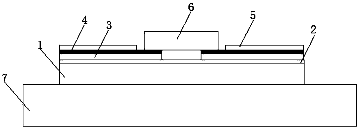
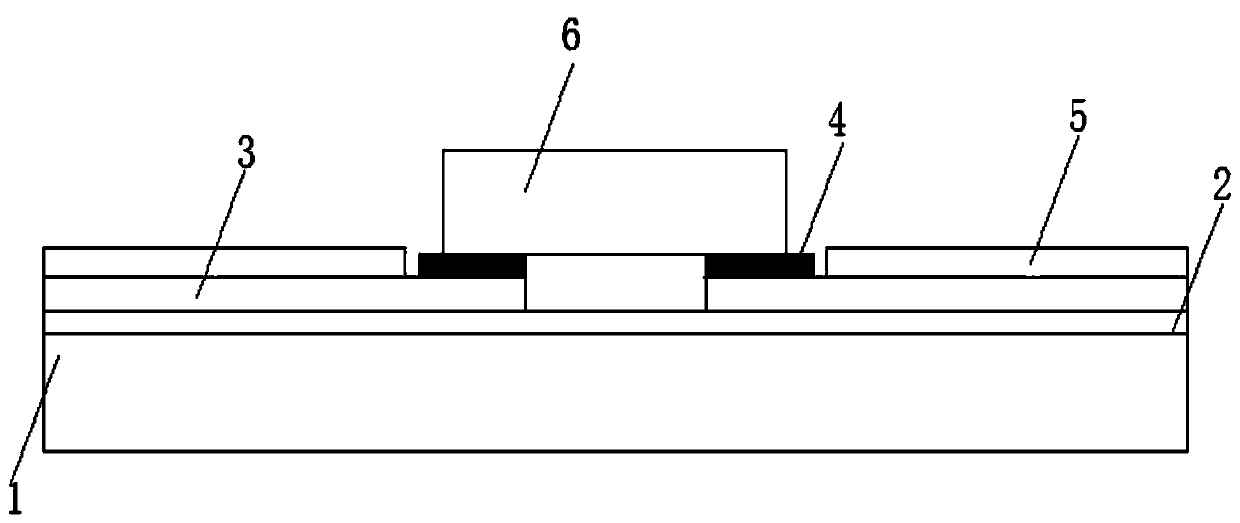
[0024] see figure 1 As shown, an LED flip-chip substrate includes an aluminum substrate 1 and a copper conductive layer 3, the top of the aluminum substrate 1 is horizontally connected to an insulating layer 2, and the top of the insulating layer 2 is horizontally connected to a copper conductive layer 3 , the top of the copper conductive layer 3 is provided with a tin layer 4;

[0025] A groove is provided at the top and middle end of the copper conductive layer 3 , and a flip chip 6 is connected to the upper part of the ...


PUM

PropertyMeasurementUnit
Thicknessaaaaaaaaaa

Abstract

The invention discloses an LED inverted substrate, which comprises an aluminum substrate and a copper conductive layer. The top of the aluminum substrate is horizontally connected with an insulating layer. The top of the insulating layer is horizontally connected with the copper conductive layer. A tin layer is arranged on the top of the copper conductive layer. A groove is arranged in the top middle of the copper conductive layer, and the upper part of the copper conductive layer is connected with a flip chip through the groove. The tin layer does not change color after oxidation, and does not affect the product performance. No solder paste is needed during die bonding on the tin layer. The tin layer has a great cost advantage over silver/gold. The thickness of the tin layer is controllable and usually within 8-25 microns. Compared with solder paste having a thickness of 100-130 microns, the tin layer has a shorter heat conduction path. The temperature of a heating block is 230 DEG C,which will not change the color of the ink and can make the flip chip conduct electricity evenly in use.

Description

technical field [0001] The invention relates to a flip-chip substrate, in particular to an LED flip-chip substrate, belonging to the field of LED lamp processing applications. Background technique [0002] In recent years, flip-chip LED technology with smaller size, denser arrangement and greater current resistance has been widely used in various fields. The existing LED flip-chip substrate is aluminum-based copper plate, in which the aluminum base plays the role of heat conduction and heat dissipation , There is an insulating layer between the aluminum base and the copper plate, which plays the role of isolating current, and the copper plate is a conductive layer, which plays a conductive role. The surface of the copper plate in the non-welding area is covered with ink to protect the copper plate from external influences such as scratches, oxidation, and salt spray. The copper layer is exposed in the area. To reserve a groove, the die bonder drips the solder paste onto the ...

Claims


Application Information

Patent Timeline
IPC IPC(8): H01L33/62
CPCH01L33/62H01L2224/29111H01L2933/0066
Inventor 訾青松吴疆丁磊
Owner ANHUI COREACH TECH
Why Eureka
Try Eureka