SCR denitration system
A technology of denitration and rectification grid, applied in the field of SCR denitration system, can solve the problems of ammonia escape, air preheater blockage, low denitration efficiency, etc., and achieve the effect of improving reaction efficiency, reducing ammonia overflow and improving denitration efficiency.
- Summary
- Abstract
- Description
- Claims
- Application Information
AI Technical Summary
Problems solved by technology
Method used
Image
Examples
Embodiment 1
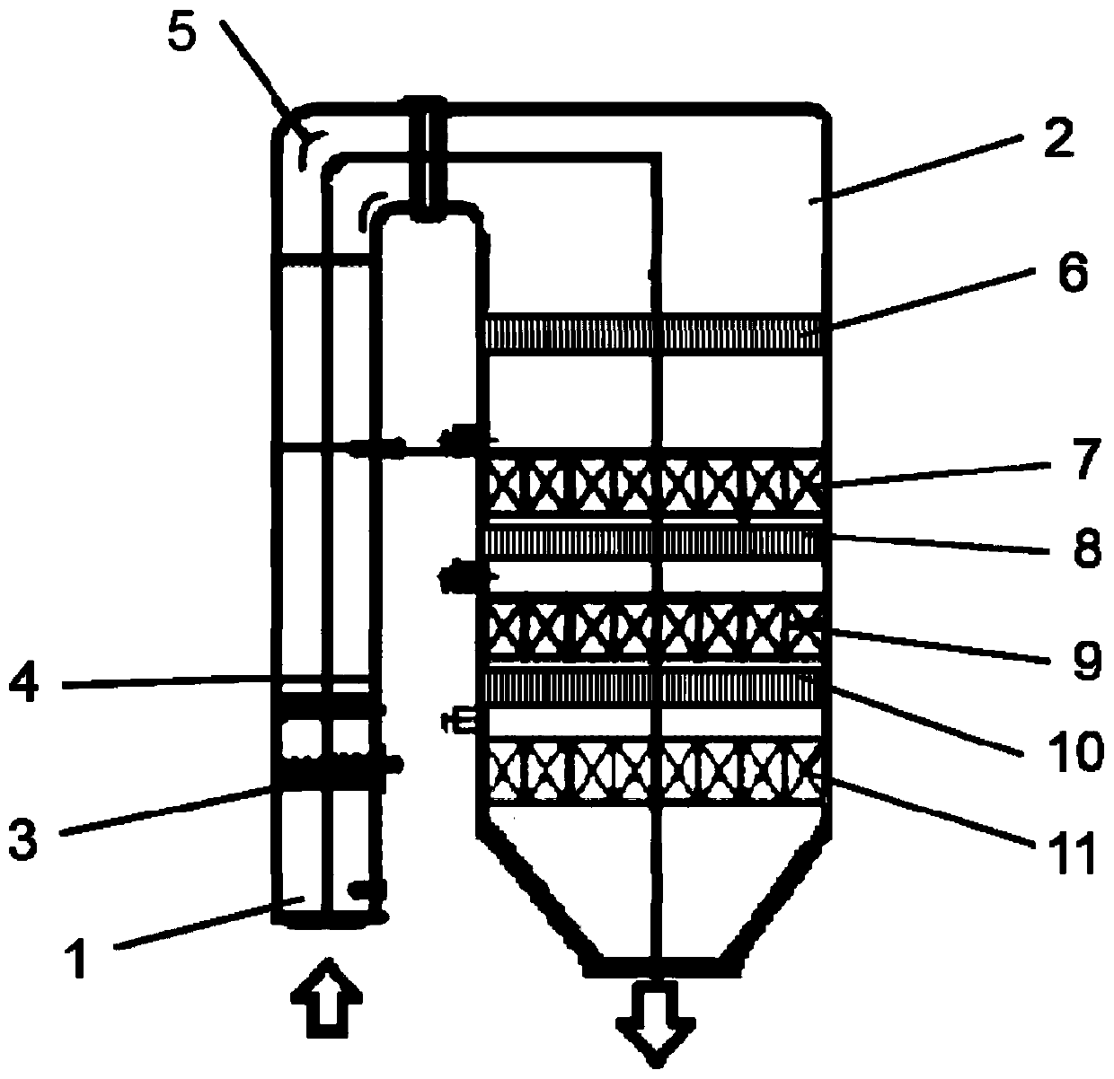
[0047] This embodiment provides an SCR denitrification system, such as figure 1 As shown, it includes a main body 2. The main body 2 includes a flow section and a reaction section connected in sequence. The end of the flow section away from the reaction section is the flue gas inlet 1, and the end of the reaction section far away from the flow section is the flue gas outlet. Also includes,
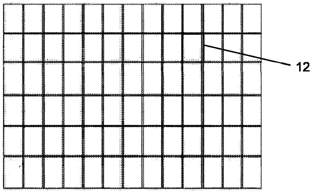
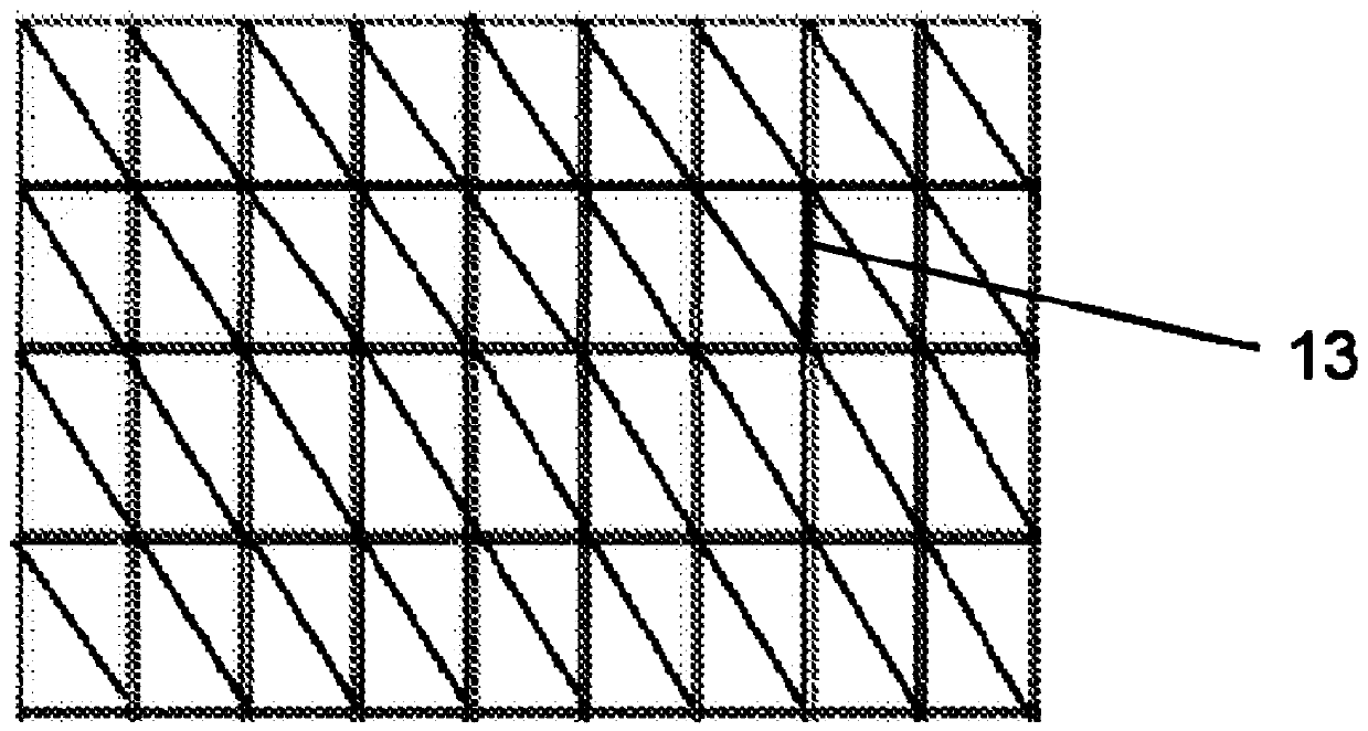
[0048] The first mixing unit includes a first rectifying grid 6 and a first static mixer 4, the first rectifying grid 6 is arranged in the reaction section, and the first static mixer 4 is arranged in the circulation section near the flue gas inlet 1;
[0049] The first catalyst layer 7 and the second mixing unit 8, the second mixing unit 8 is arranged in the reaction section, and the first catalyst layer 7 is arranged between the first rectifying grid 6 and the second mixing unit 8 and is located in the reaction section , the second mixing unit 8 is a second rectifying grid or a second s...
Embodiment 2
[0059] This embodiment provides an SCR denitrification system. On the basis of the above-mentioned embodiment 1, the system further includes a third catalyst layer 11 disposed in the reaction section and disposed away from the first catalyst layer 7 relative to the second catalyst layer 9 . By setting the third catalyst layer 11, the unreacted NOx and NH passing through the first catalyst layer 7 and the second catalyst layer 9 3 The reaction is carried out again in the third catalyst layer 11, thereby avoiding unreacted NOx and NH 3 Directly discharged, effectively reducing the amount of ammonia overflow and improving the denitrification efficiency of the system.
Embodiment 3
[0061] This embodiment provides an SCR denitrification system, such as figure 1 As shown, on the basis of the above-mentioned embodiment 2, the system further includes a third mixing unit 10, which is arranged in the reaction section and is arranged between the second catalyst layer and the third catalyst layer, and the third mixing unit 10 is the third Rectification grid or third static mixer. In this embodiment, the second static mixer includes, but is not limited to, square blade or circular blade mixers.
[0062] In the above SCR denitration system, the second mixing unit 8 is arranged between the first catalyst layer 7 and the second catalyst layer 9 , and the third mixing unit 10 is arranged between the second catalyst layer 9 and the third catalyst layer 11 . Unreacted NOx and NH after flowing through the first catalyst layer 3 Mix again when passing through the second mixing unit 8, so that there is a more uniform velocity field and concentration field when passing t...
PUM
| Property | Measurement | Unit |
|---|---|---|
| Height | aaaaa | aaaaa |
Abstract
Description
Claims
Application Information
 - R&D
- Intellectual Property
- Life Sciences
- Materials
- Tech Scout
- Unparalleled Data Quality
- Higher Quality Content
- 60% Fewer Hallucinations
Browse by: Latest US Patents, China's latest patents, Technical Efficacy Thesaurus, Application Domain, Technology Topic, Popular Technical Reports.
© 2025 PatSnap. All rights reserved.Legal|Privacy policy|Modern Slavery Act Transparency Statement|Sitemap|About US| Contact US: help@patsnap.com


