
Multi-mode curved surface phased array ultrasonic tomography device

A technology of ultrasonic tomography and phased array, which is applied in measuring devices, analyzing solids using sound waves/ultrasonic waves/infrasonic waves, and using sound waves/ultrasonic waves/infrasonic waves for material analysis. It can solve monitoring and distribution parameter estimation, and a single test mode , ultrasonic tomography and other problems, to achieve the effect of strong anti-electromagnetic interference, rich modulation information, and broaden the scope of application

Inactive Publication Date: 2019-11-19
TIANJIN UNIV
View PDF3 Cites 6 Cited by
  • Summary
  • Abstract
  • Description
  • Claims
  • Application Information

AI Technical Summary

Problems solved by technology

[0005] At present, the existing ultrasonic tomography device mainly uses a single probe to excite at a single frequency, and records the data collected in the corresponding transmission or reflection mode, which has the defects of small data volume and single test mode
In addition, the existing ultrasonic tomography device has no ability to adjust the sound field, and cannot form an excitation sound field with dynamically adjustable direction, angle, amplitude, and frequency, and thus cannot obtain the multi-sensitive modulation information of the contents to different excitation sound fields
The defects of the above-mentioned test devices lead to the poor effect and low precision of ultrasonic tomography of oil-gas-water multiphase media, and it is impossible to perform real-time flow state monitoring and distribution parameter estimation

Method used


Image

  • Multi-mode curved surface phased array ultrasonic tomography device
  • Multi-mode curved surface phased array ultrasonic tomography device
  • Multi-mode curved surface phased array ultrasonic tomography device

Examples


Embodiment Construction

[0021] The multi-mode curved phased array ultrasonic tomography device of the present invention will be described with reference to the accompanying drawings and embodiments, and is intended to be described as an embodiment of the present invention, not the only form that can be manufactured or utilized, and the same function can be achieved for other The embodiments of the invention should also be included within the scope of the present invention.

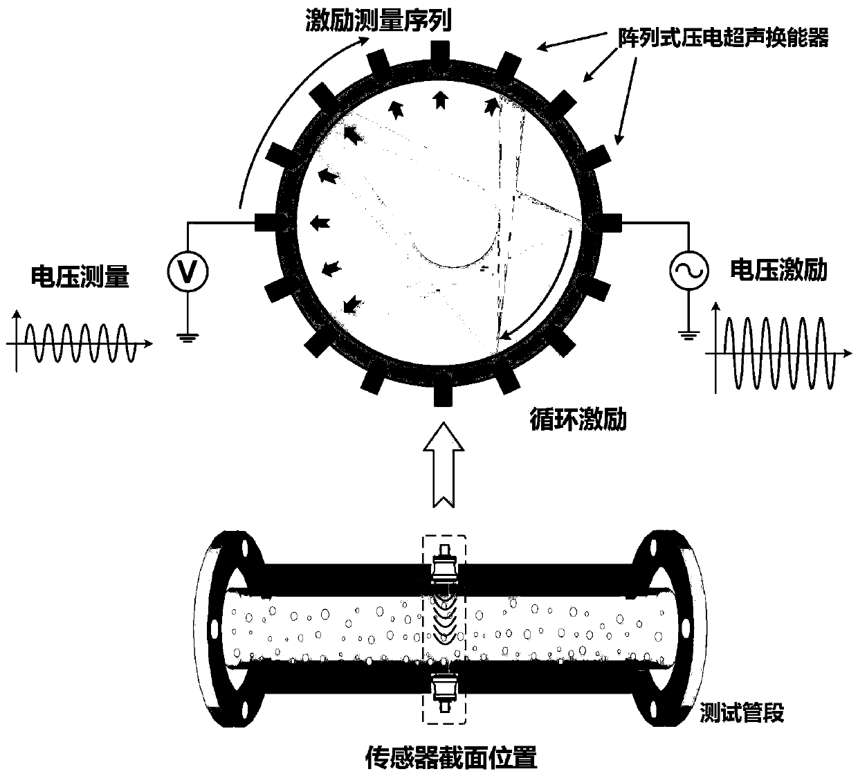
[0022] figure 1 It is the basic test principle diagram of the device of the present invention, including the test tube section, a set of ultrasonic transducer arrays with 64 probes of single section. The probe array is composed of 64 independent ultrasonic transducers, which are evenly distributed along the outer wall of the pipe in the same pipe section, and the angle between adjacent sensors is the same. The excitation signal of each probe is individually modulated, and the sound pressure response of each probe is collected. ...


PUM


Abstract

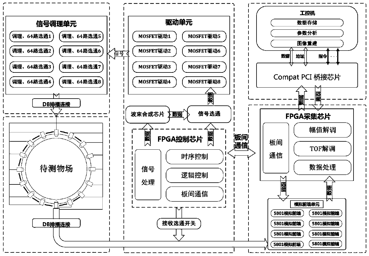
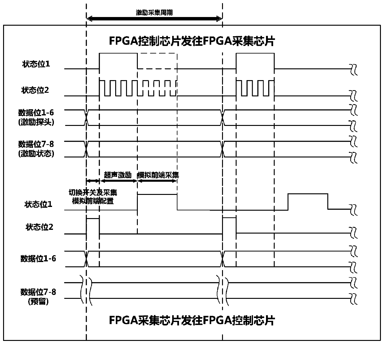
The invention relates to a multi-mode curved surface phased array ultrasonic tomography device. The device is used for reconstructing the phase distribution of oil-gas-water three-phase fluid flowingthrough the to-be-measured section of a pipeline. The multi-mode curved surface phased array ultrasonic tomography device comprises an ultrasonic sensor array, a signal control module, a high-voltageexcitation module, a signal acquisition and demodulation module, an industrial bus and an upper computer module; different modes of the signal control module can be gated, so that the signal control module can control the excitation and measurement processes of all the other modules and the sensor array through a fixed time sequence; under the control of the signal control module, the high-voltageexcitation module generates excitation voltage signals of which the duration, frequency and duty ratio are adjustable, and applies the excitation voltage signals to excitation ultrasonic sensors; induction voltage signals received by the ultrasonic sensors are recorded, processed and subjected to analog-to-digital conversion through the signal acquisition and demodulation module; and obtained digital signals are transmitted to an FPGA control chip in the signal control module; and therefore, demodulation can be completed.

Description

technical field [0001] The invention belongs to the field of multiphase flow process tomography, and relates to the realization of a multi-mode curved phased array ultrasonic tomography measurement device, which can realize high-precision visual measurement of multiphase flow phase distribution and online estimation of distribution parameters. The present invention is aimed at, but not limited to, the widely existing oil-gas-water three-phase multiphase flow process, and the measuring device of the present invention is still applicable to the multiphase flow phenomenon existing in other industrial processes and chemical reactions. Background technique [0002] Multiphase flow phenomenon widely exists in modern engineering fields and equipment such as bioengineering, oil and gas exploration, chemical industry, metallurgical industry, food processing, etc., and plays a very important role in industrial production and scientific research. Accurate detection of flow process param...

Claims


Application Information

Patent Timeline
IPC IPC(8): G01N29/06G01N29/34
CPCG01N29/0672G01N29/34
Inventor 董峰刘皓谭超
Owner TIANJIN UNIV
Learn More