Passivated contact solar cell and preparation method thereof

A technology for solar cells and passivation layers is applied in the field of solar cells and can solve the problems of reducing the deposition rate of doped polysilicon layers, reducing the photoelectric conversion efficiency, and increasing the recombination of silicon substrates.

Inactive Publication Date: 2019-11-19
ZHEJIANG ASTRONERGY +1
View PDF4 Cites 19 Cited by
  • Summary
  • Abstract
  • Description
  • Claims
  • Application Information

AI Technical Summary

Problems solved by technology

[0004] Forming a doped polysilicon layer by in-situ doping is a conventional method used in the solar cell industry. While growing an intrinsic polysilicon layer, a gas containing impurities, such as pH 3 and B 2 h 6 , but the impurity gas will also bring adverse effects at the same time, which will reduce the deposition rate of the doped polysilicon layer, and when the doped ions are annealed at high temperature, they will easily diffuse into the silicon substrate, increasing the recombination of the silicon substrate, resulting in TOPCon battery The photoelectric conversion efficiency decreases

Method used


Image

  • Passivated contact solar cell and preparation method thereof
  • Passivated contact solar cell and preparation method thereof

Examples


Embodiment Construction

[0047] In order to enable those skilled in the art to better understand the solution of the present application, the present application will be further described in detail below in conjunction with the drawings and specific implementation methods. Apparently, the described embodiments are only some of the embodiments of this application, not all of them. Based on the embodiments in this application, all other embodiments obtained by persons of ordinary skill in the art without making creative efforts belong to the scope of protection of this application.

[0048] In the following description, a lot of specific details are set forth in order to fully understand the present invention, but the present invention can also be implemented in other ways different from those described here, and those skilled in the art can do it without departing from the meaning of the present invention. By analogy, the present invention is therefore not limited to the specific examples disclosed bel...


PUM

PropertyMeasurementUnit
thicknessaaaaaaaaaa
thicknessaaaaaaaaaa
thicknessaaaaaaaaaa

Abstract

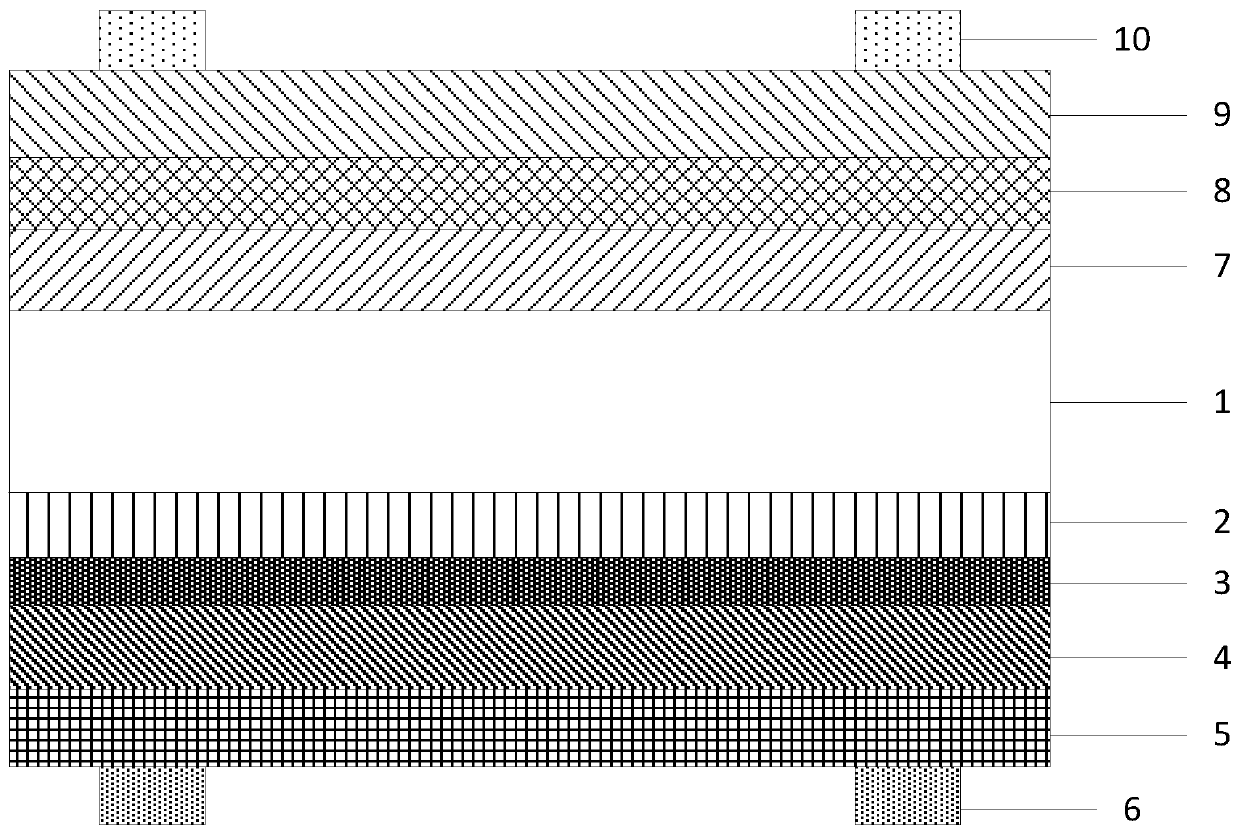
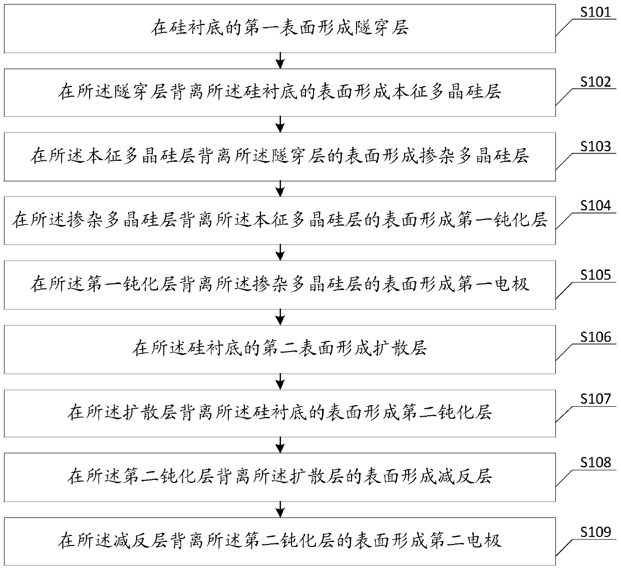
The present application discloses a passivated contact solar cell comprising a silicon substrate; a tunneling layer on the first surface of the silicon substrate; an intrinsic polycrystalline siliconlayer on the surface of the tunneling layer away from the silicon substrate; a doped polycrystalline silicon layer on a surface of the tunneling layer away from the intrinsic polycrystalline silicon layer; a first passivation layer on a surface of the doped polycrystalline silicon layer away from the intrinsic polycrystalline silicon layer; a first electrode on a surface of the first passivation layer away from the doped polycrystalline silicon layer; a diffusion layer on the second surface of the substrate; a second passivation layer on a surface of the diffusion layer away from the silicon substrate; an antireflection layer on a surface of the second passivation layer away from the diffusion layer; and a second electrode on a surface of the antireflection layer away from the second passivation layer. The intrinsic polycrystalline silicon layer is disposed between the tunneling layer and the doped polycrystalline silicon layer so as to improve the deposition rate of the doped polycrystalline silicon layer, reduce the diffusion of impurity ions to the silicon substrate, reduce the recombination of the silicon substrate, thereby improving photoelectric conversion efficiency. The present application also provides a preparation method having the above advantages.

Description

technical field [0001] The present application relates to the technical field of solar cells, in particular to a passivated contact solar cell and a preparation method thereof. Background technique [0002] Solar cells can convert solar energy into electrical energy, and the entire conversion process will not produce any waste water and waste residues and other pollutants. Under the dual crises of energy and the environment, the solar cell industry has developed rapidly, and improving the photoelectric conversion efficiency of solar cells has become a solar cell industry. A goal that is constantly pursued. [0003] Tunnel oxide passivated contact (Tunnel Oxide Passivated Contact, TOPCon) cell is a relatively efficient solar cell. The back of the TOPCon cell is composed of a passivated contact structure of tunnel oxide layer and doped polysilicon layer. The tunnel oxide layer can Selective transport of carriers, shielding multiple carriers, plays an effective passivation rol...

Claims


Application Information

Patent Timeline
Patent Type & Authority Applications(China)
IPC IPC(8): H01L31/028H01L31/0216H01L31/0236H01L31/068H01L31/18
CPCH01L31/02167H01L31/02168H01L31/02366H01L31/028H01L31/068H01L31/1804H01L31/1868Y02E10/546Y02E10/547Y02P70/50
Inventor 李宏伟翁高登马玉超何胜周盛永徐伟智
Owner ZHEJIANG ASTRONERGY
Why Eureka
Try Eureka