Landing section cable laying system and laying method

A technology of cable laying and landing section, applied in the direction of cable laying equipment, etc., can solve the problems of limiting the speed of cable pulling, increasing the workload of manpower, and shortening the time of cable laying operations, so as to avoid time constraints and increase operation time , The effect of reasonable arrangement of construction time and work and rest time

Pending Publication Date: 2019-11-19
北京海瑞兴能源科技有限责任公司 +1
View PDF1 Cites 2 Cited by
  • Summary
  • Abstract
  • Description
  • Claims
  • Application Information

AI Technical Summary

Problems solved by technology

On the other hand, for the long-distance intertidal zone, it generally takes 5 to 10 days or even longer to lay cables. The time in which cable laying work can be carried out is further shortened
[0018] Finally, when carrying out the cable pulling operation, it is necessary to bind the floating tire on the cable at the beginning of the transition ditch, and to remove the floating tire from the cable at the end of the transition ditch, which not only increases the manpower workload, but also limits the cable pull. pulling speed

Method used


Image

  • Landing section cable laying system and laying method
  • Landing section cable laying system and laying method
  • Landing section cable laying system and laying method

Examples


Embodiment 1

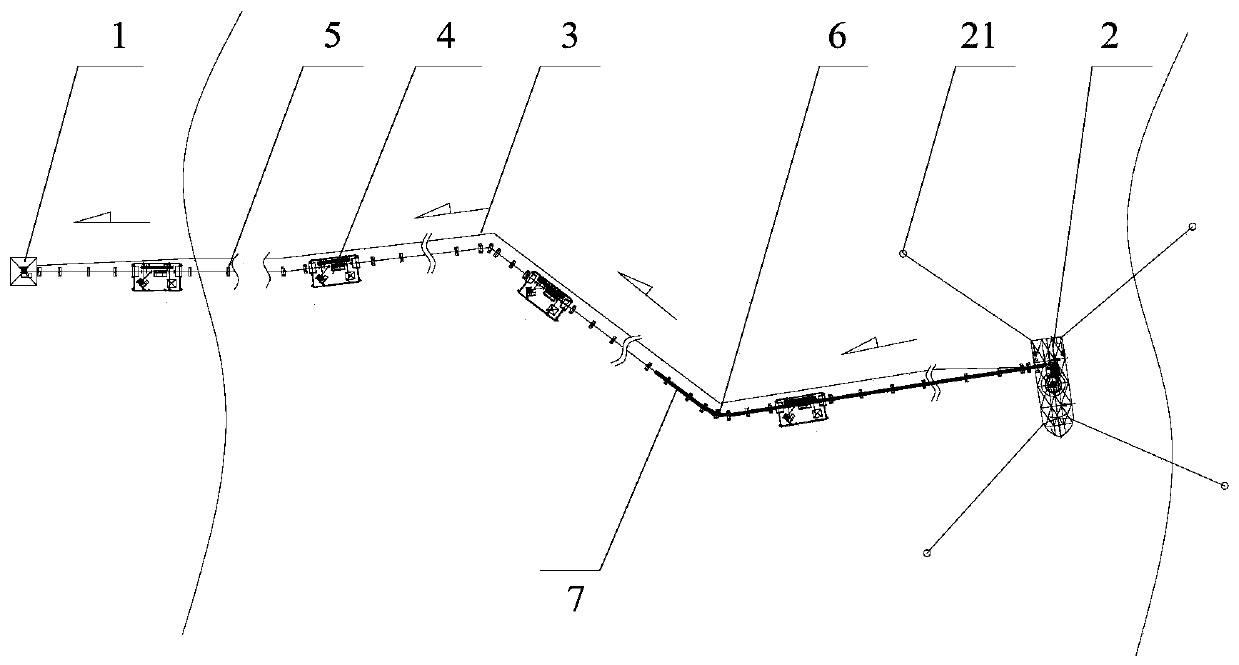
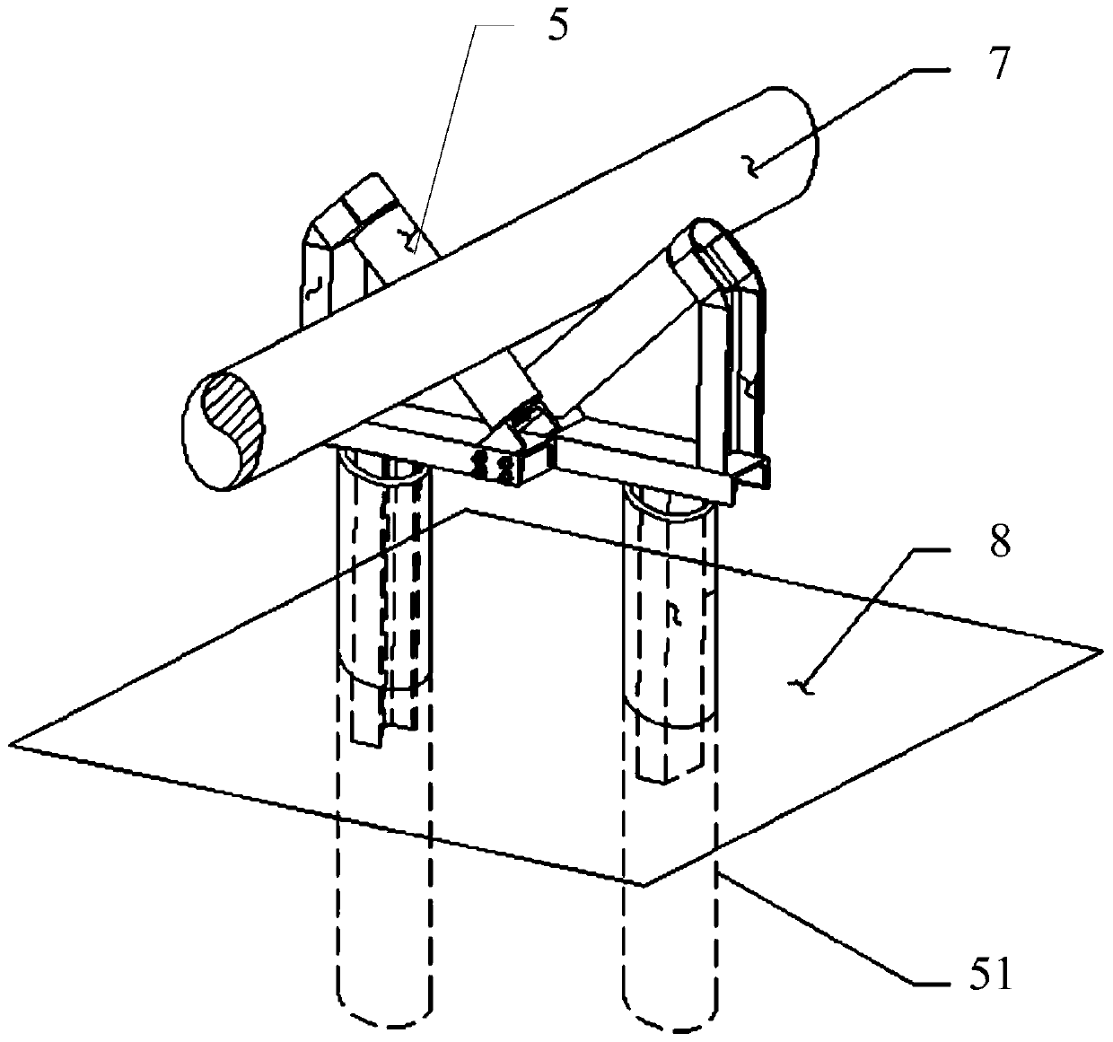
[0071] like figure 1 , 3 As shown in -4, a cable laying system for the landing section provided by the present invention includes a land terminal 1, a cable laying ship 2 and a plurality of cable pulling brackets, and the lower end of each cable pulling bracket is a pipe pile 51, which is used for Fixed in the soil interface 8, the upper end is provided with a bracket structure for supporting the cable 7; a plurality of cable pulling brackets are arranged at intervals along the cable design route 3 connecting the land terminal 1 and the cable laying ship 2, forming a cable pulling bracket. Pulling channel; the cable pulling channel includes a plurality of straight segments, and a broken line is formed between a plurality of straight segments; a pulling device 4 is arranged at each straight segment of the cable pulling channel, so The pulling device 4 is used to pull the cable 7 from the cable laying ship 2 to the direction of the land terminal 1 .

[0072] In this embodiment...

Embodiment 2

[0088] The present invention provides a cable laying method for the landing section, which has the above-mentioned cable laying system for the landing section, including the following steps:

[0089] (1) At low tide, set up a cable pulling channel, install pulling device 4 and land terminal 1;

[0090] (2) When the tide is high, the cable laying ship 2 is positioned;

[0091] (3) At the next low tide, start the laying system of the cable laying ship 2, so that the end of the cable is lowered to the end of the cable pulling channel close to the cable laying ship 2;

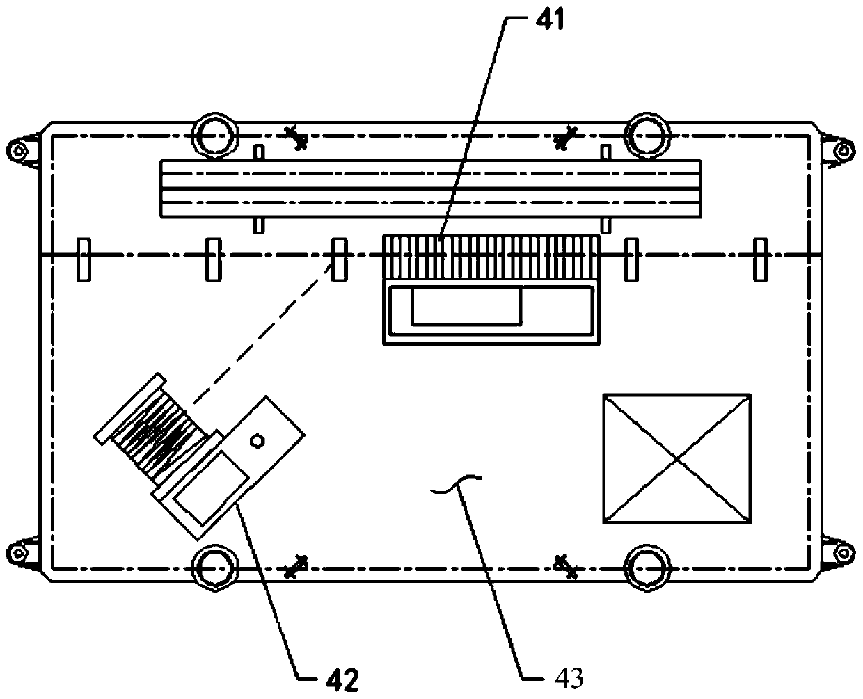
[0092] (4) pull the twisted rope of the winch mill 42 on the first pulling device 4 to the cable end of the cable laying ship 2 along the cable pulling passage, and connect with the cable end;

[0093](5) Start the winch 42, pull the end of the cable to the first pulling device 4 along the cable pulling channel, and enter into the first pulling device 4 On tractor 41;

[0094] (6) move the movable end of the twi...


PUM


Abstract

The invention relates to the submarine cable laying technology field and especially relates to a landing section cable laying system and a laying method. The system comprises a land terminal, a cable-laying ship, and multiple cable pulling brackets. A lower end of each cable pulling bracket is a pipe pile used for fixing in a soil interface, and an upper end is provided with a holding groove structure for holding and supporting a cable. The multiple cable pulling brackets are arranged along a cable design route which is connected between the land terminal and the cable-laying ship at intervalsto form a cable pulling channel. The cable pulling channel includes a plurality of straight segments, and the plurality of straight segments form a broken line shape. A pulling device is arranged ateach straight segment of the cable pulling channel, and a pulling device is used to pull the cable from the cable-laying ship towards the land terminal. The landing section cable laying system and thelaying method of the invention do not rely on a tidal action of sea through pulling the cable in the cable pulling channel and avoid a tide restriction, and operation time is increased, which is goodfor reducing a construction period and reasonably arranging a construction schedule.

Description

technical field [0001] The invention relates to the technical field of submarine cable laying, in particular to a cable laying system and a laying method for a landing section. Background technique [0002] The laying of the submarine cable landing section usually adopts the method of first pulling and then laying. Its basic method steps are: [0003] 1. Landing on the beach: the cable-laying ship uses the high tide period to land on the beach to shorten the distance of the cable landing section as much as possible; the cable-laying ship is in place through the mooring system as the starting point for cable landing pull; [0004] 2. Landing pulling: use the pulling equipment of the land terminal and the transfer platform to pull the cable released from the cable laying ship to the land terminal along the cable design route; [0005] 3. Cable laying and burial: dig a trench at the cable design route, lift the cable into the trench, and then lay and bury it. [0006] Landin...

Claims


Application Information

Patent Timeline
Patent Type & Authority Applications(China)
IPC IPC(8): H02G1/10
CPCH02G1/10
Inventor 柴宝亮李大钧李雪亮王伟王大元肖遥
Owner 北京海瑞兴能源科技有限责任公司
Why Eureka
Try Eureka