Laser diode power supply structure

A technology of laser diodes and power supplies, which is applied in lasers, laser components, semiconductor lasers, etc., can solve the problems of expensive driver ICs, high costs, and low efficiency, and achieve the effects of easy procurement, low cost, and convenient adjustment

Pending Publication Date: 2019-11-19
UNION OPTECH
View PDF0 Cites 0 Cited by
  • Summary
  • Abstract
  • Description
  • Claims
  • Application Information

AI Technical Summary

Problems solved by technology

[0002] At present, most laser diodes are driven by integrated ICs, which have high cost and relatively low efficiency. The price of driving ICs with high current output is extremely expensive, and t

Method used


Image

  • Laser diode power supply structure
  • Laser diode power supply structure

Examples


Embodiment Construction

[0014] The features of the present invention and other relevant features are described in further detail below through the embodiments, so as to facilitate the understanding of those skilled in the art:

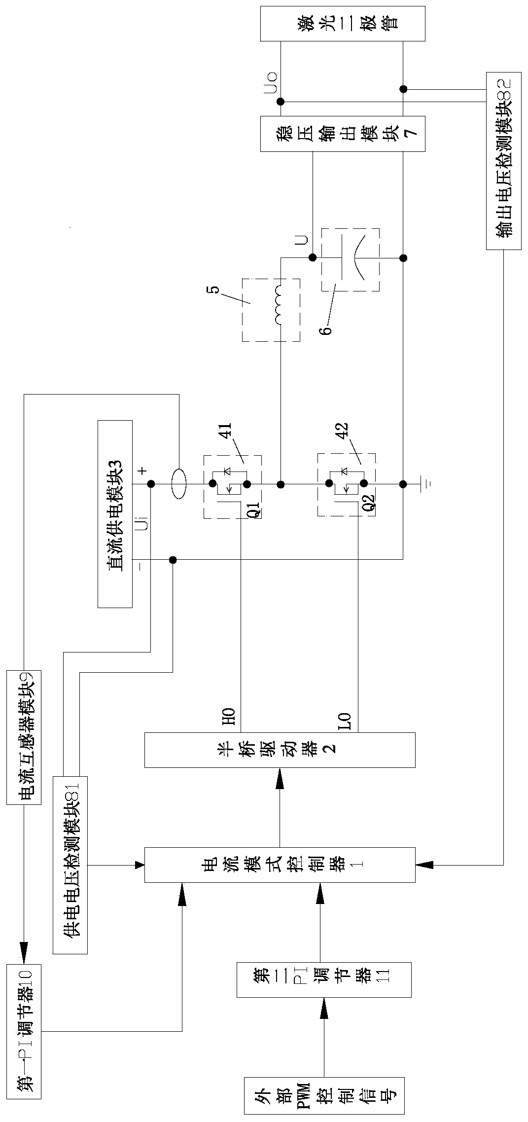
[0015] like figure 1 and figure 2 As shown, a laser diode power supply structure includes a current mode controller 1, a half-bridge driver 2 controlled by the current mode controller 1, and a positive voltage output terminal and a negative voltage connected to a DC power supply module 3 in sequence. The controlled high-side MOS transistor switch module 41 and the controlled low-side MOS transistor switch module 42 between the output connection terminals and driven by the half-bridge driver 2, the positive pole voltage of the controlled low-side MOS transistor switch module 42 is connected to An energy storage inductance 5 and a polar capacitor 6 are sequentially connected between the terminal and the negative voltage connection terminal, and a voltage stabilizing output mo...


PUM


Abstract

The invention discloses a laser diode power supply structure. The structure is simple and is easy to realize. A current mode controller is used to generate high current totem pole output, and the totem pole output of the current mode controller drives a half-bridge driver to drive high and low side MOS tubes to achieve a purpose of adjusting a laser diode current. The current mode controller, thehalf-bridge driver, and the MOS tube are easy to purchase and cost is low. A high-side MOS tube and a low-side MOS tube are alternately conducted so that an energy storage inductor side forms an alternating voltage with an amplitude of Ui/2. A duty cycle of a switch is changed so that an average value of an output voltage u can be changed and an output voltage Uo is also changed, and adjusting isconvenient.

Description

【Technical field】 [0001] The invention relates to a laser diode power supply structure. 【Background technique】 [0002] At present, most laser diodes are driven by integrated IC, which has high cost and relatively low efficiency. The price of driving IC with high current output is extremely expensive, and the price of a single IC is more than one hundred. Therefore, how to overcome the above-mentioned defects has been Become an important issue urgently to be solved by those skilled in the art. 【Content of invention】 [0003] The invention overcomes the disadvantages of the above technologies and provides a laser diode power supply structure. [0004] To achieve the above object, the present invention adopts the following technical solutions: [0005] A laser diode power supply structure, including a current mode controller 1, a half-bridge driver 2 controlled by the current mode controller 1, and a positive voltage output connection terminal and a negative voltage output...

Claims


Application Information

Patent Timeline
IPC IPC(8): H02M1/088H01S5/042
CPCH01S5/042H02M1/088
Inventor 郑旭东邱盛平邹艳华王强苏能斌孔祥锐肖阳阳
Owner UNION OPTECH
Why Eureka
Try Eureka