Processing clamping device for thin-walled framework and clamping method

A clamping device and frame technology, applied in positioning devices, metal processing equipment, metal processing machinery parts, etc., can solve the problem that the clamping method does not have the transmission of the rotational torque of the machine tool, the main coil frame cannot be processed at one time, and the outer circle of the frame is installed To avoid problems such as clamping deformation, achieve the effect of convenient clamping, avoid concentricity errors at both ends, and avoid clamping and processing deformation

Pending Publication Date: 2019-11-22
CSSC NANJING LUZHOU MACHINE
View PDF0 Cites 7 Cited by
  • Summary
  • Abstract
  • Description
  • Claims
  • Application Information

AI Technical Summary

Problems solved by technology

[0003] One is that the outer circle of the frame needs to be clamped from one end. When processing the outer circle of the other end, the frame needs to be turned around to re-clamp the outer circle that has been processed, and then process the outer circle of the unprocessed end again. The main coil frame cannot be processed at one time. low precision;
[0004] The second is that the existing clamping method clamps the outer circle of the frame, so that the outer circle of the frame with high precision requirements has a slight clamping deformation, and the clamping marks on the surface are obvious;
[0005] The third is that the existing clamping method does not fundamentally solve the transmission of the rotational torque of the machine tool. The thin-walled frame and support are still the main body of the rotational torque, and there is still obvious distortion and deformation after processing.

Method used


Image

  • Processing clamping device for thin-walled framework and clamping method
  • Processing clamping device for thin-walled framework and clamping method
  • Processing clamping device for thin-walled framework and clamping method

Examples


Embodiment 1

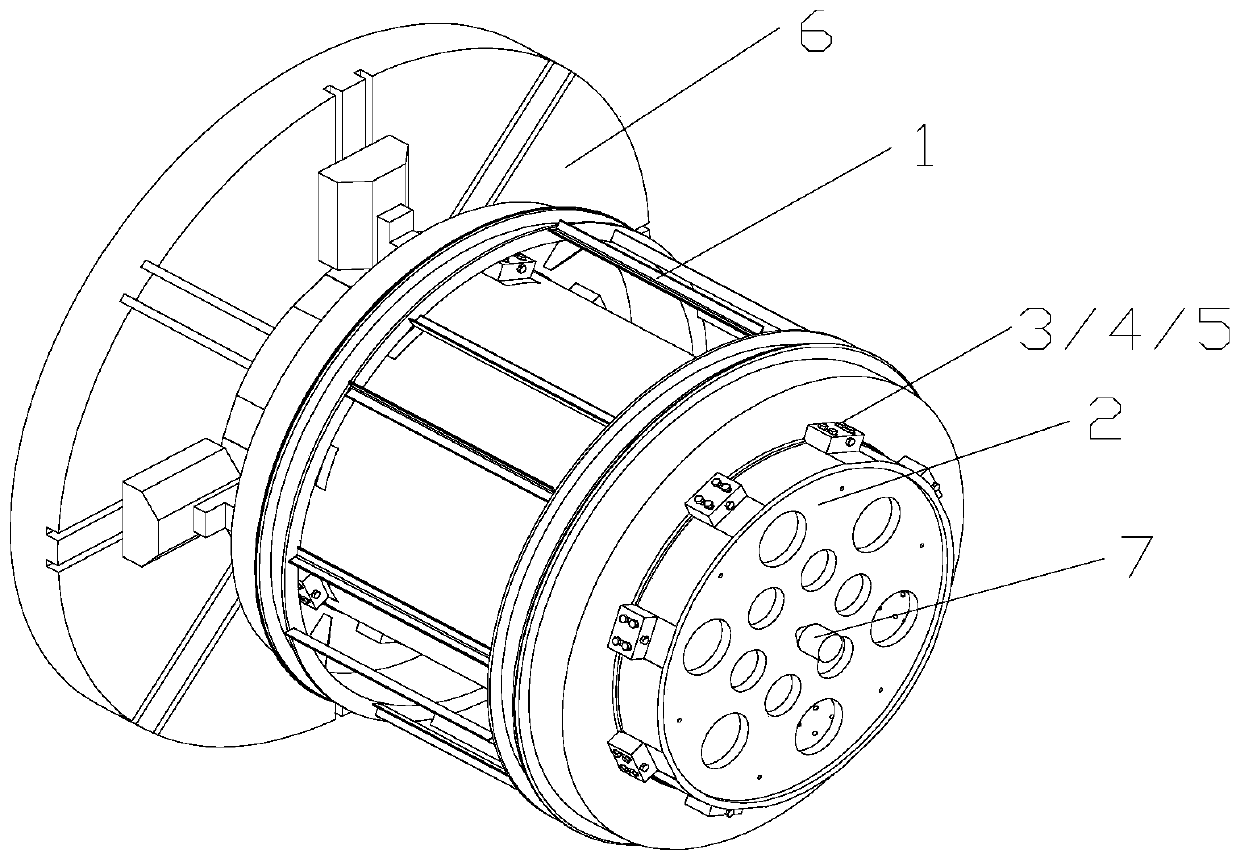
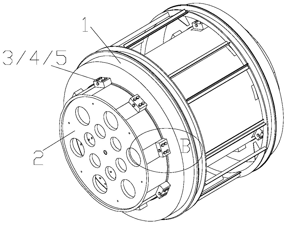
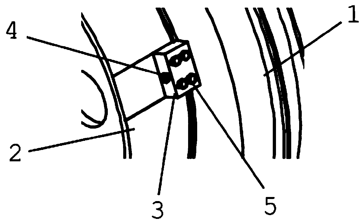
[0041] Such as figure 1 , figure 2 , Figure 6 , Figure 7 , Figure 8 and Figure 9 As shown, a processing and clamping device for a thin-walled frame includes a main coil clamping cylinder 2, sixteen positioning block assemblies 3, and sixteen sets of positioning block mounting bolts 5 corresponding to the positioning block assemblies 3 and Sixteen sets of main coil clamping bolts4. Sixteen positioning block assemblies 3 are divided into two groups, which are evenly arranged on the outer circumferential surface of the main coil clamping cylinder 2 along the circumferential direction. The main coil clamping cylinder 2 is installed inside the main coil frame 1, and the main coil clamping The length of the barrel 2 is greater than that of the main coil frame 1 . The positioning block assembly 3 is composed of a symmetrically arranged outer positioning block 301 and an inner positioning block 302. The outer positioning block 301 and the inner positioning block 302 are res...


PUM


Abstract

The invention relates to a processing clamping device for a thin-walled framework. The device comprises a main coil clamping tube mounted inside a main coil framework, wherein a plurality of positioning block components distributed along the peripheral direction are arranged on the outer peripheral surface of the main coil clamping tube; the positioning block components comprise outer side positioning blocks and inner side positioning blocks which are symmetrically arranged; the outer side positioning blocks and the inner side positioning blocks are separately connected with the main coil framework through main coil clamping bolts; and the outer side positioning blocks and the inner side positioning blocks are separately fixedly connected with the main coil clamping tube through positioning block mounting bolts. The device has the advantages that the device can not only avoid clamping damage to high precision outer periphery caused by direct clamping of the outer peripheral surface ofthe thin-walled framework, but also realize the fact that processing of two ends of the thin-walled framework is accomplished at one step after the thin-walled framework is clamped, avoids concentricity error at the two ends caused by turning processing of a workpiece, and thoroughly solves twist deformation to the workpiece by the rolling torque of a machine tool.

Description

technical field [0001] The invention relates to the clamping of a thin-walled frame on a horizontal processing lathe, in particular to a processing and clamping device and a clamping method of a thin-walled frame, belonging to the technical field of mechanical processing. Background technique [0002] The clamping of the existing thin-walled frame on the horizontal processing lathe is usually to weld multiple supports inside the frame to increase the rigidity of the frame and reduce the deformation of the frame. When the existing clamping method is processed, it has the following disadvantages [0003] One is that the outer circle of the frame needs to be clamped from one end. When processing the outer circle of the other end, the frame needs to be turned around to re-clamp the outer circle that has been processed, and then process the outer circle of the unprocessed end again. The main coil frame cannot be processed at one time. low precision; [0004] The second is that ...

Claims


Application Information

Patent Timeline
Patent Type & Authority Applications(China)
IPC IPC(8): B23Q3/06B23Q3/12
CPCB23Q3/06B23Q3/062B23Q3/065B23Q3/12
Inventor 张进利马晅何娟娟袁垚秦汉耿志辉
Owner CSSC NANJING LUZHOU MACHINE
Why Eureka
Try Eureka