
Anti-icing wind turbine blade, and method for preventing wind turbine blade from icing

A technology for wind power blades and anti-icing, which is applied to wind power generation, wind power engines consistent with the wind direction, wind power engines, etc., which can solve the inconvenience of preventing wind power blades and wind power blades from freezing, affect the power generation efficiency of wind power units, and fail to achieve technical effects and other problems, to achieve good anti-icing effect, convenient operation and wide application range

Pending Publication Date: 2019-11-22
GUODIAN UNITED POWER TECH
View PDF0 Cites 0 Cited by
  • Summary
  • Abstract
  • Description
  • Claims
  • Application Information

AI Technical Summary

Problems solved by technology

But for large megawatt-scale wind turbine blades, this method of melting ice cannot achieve the technical effect of understanding
Moreover, the existing methods all need to be operated in the shutdown state of the wind turbine, which affects the power generation efficiency of the wind turbine.
[0004] This shows that above-mentioned existing wind power blade and the method for preventing icing of wind power blade still have inconvenience and defect, and urgently need to be further improved

Method used


Image

  • Anti-icing wind turbine blade, and method for preventing wind turbine blade from icing
  • Anti-icing wind turbine blade, and method for preventing wind turbine blade from icing
  • Anti-icing wind turbine blade, and method for preventing wind turbine blade from icing

Examples


Embodiment Construction

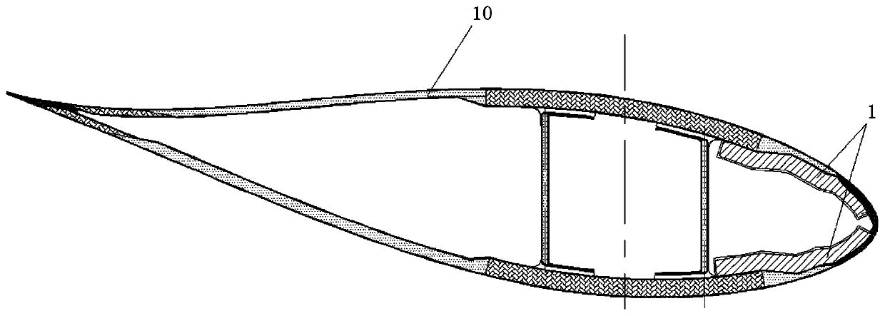
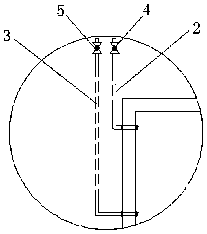
[0031] Refer to attached Figures 1 to 4 As shown, the specific structure of the anti-icing wind turbine blade in this embodiment is as follows. An anti-refrigeration body 1 is fixed on the inner surface of the wind power blade 10, two mutually independent pipelines 2, 3 are connected to the side wall of the anti-freezing body 1, and valves 4 are arranged on the two pipelines 2, 3 , 5, the two pipelines 2, 3 are used to inject or discharge high-density low-temperature-resistant liquid into the anti-refrigerator body 1 .

[0032] Specifically, the anti-freezing body 1 is fixedly bonded to the inner surface of the leading edge of the wind power blade 10 , and the outer shape of the anti-freezing body 1 matches the shape of the inner surface of the leading edge of the wind power blade 10 . That is, the anti-refrigeration body 1 is a box body customized according to the profile of the front edge of the blade inner cavity, and before the blade is molded, the customized box body is...


PUM


Abstract

The invention discloses an anti-icing wind turbine blade. Anti-icing box bodies are fixed to the inner surface of an anti-icing wind turbine blade body. The side wall of each anti-icing box body is connected with two pipes. Each of the two pipes is provided with a valve. The pipes are used for injecting high-density low-temperature-resistant liquid into the corresponding box bodies or dischargingthe high-density low-temperature-resistant liquid out of the box bodies. The multiple anti-icing box bodies are fixed to the inner surface of the wind turbine blade, all the pipes extend to the root part of the wind turbine blade, and the valves on all the pipes are arranged at the root part of the wind turbine blade. A separation plate is arranged inside each anti-icing box body, the separation plate is arranged perpendicular to the length direction of the wind turbine blade, and a plurality of damping holes are formed in the separation plate. The internal surface of each anti-icing box bodyand the external surface of each separation plate are both set to be rough surfaces. The invention further discloses a method for preventing the wind turbine blade from icing. According to the anti-icing wind turbine blade, and the method for preventing the wind turbine blade from icing, the liquid kinetic energy and thermal energy conversion principle is utilized, on the condition that a wind turbine generator does not stop, blade surfaces is continuously heated along with impeller rotation, the blade surfaces are prevented from icing, and the method is simple, convenient to carry out, practical and easy to operate.

Description

technical field [0001] The invention relates to the technical field of wind turbines, in particular to an anti-icing wind turbine blade and a method for preventing the wind turbine blade from icing. Background technique [0002] Wind power blades are an important part of wind turbines, and their unique aerodynamic shape plays a role in capturing wind power. When wind turbines operate at zero degrees Celsius or below zero, they will freeze if they encounter humid air, rain, salt spray, ice and snow, and freezing rain. After the wind power blades are covered with ice, not only the aerodynamic shape of the blades changes, which affects the power generation, but in severe cases, the blades will be broken due to ice overload. [0003] At present, in the wind power industry, the mainstream solutions for ice melting are as follows: 1) Use carbon fiber electric heating ice melting technology, add carbon fiber materials to the blade skin, and connect the power supply and controller....

Claims


Application Information

Patent Timeline
Patent Type & Authority Applications(China)
IPC IPC(8): F03D1/06F03D80/40
CPCF03D1/0675F03D80/40Y02E10/72
Inventor 褚景春袁凌黎江潘磊刘伟超
Owner GUODIAN UNITED POWER TECH
Learn More