Megawatt level low speed direct-driven wind turbine generator shaft system device

A wind power generator, megawatt-level technology, applied in the field of megawatt-level low-speed direct-drive wind power generator shafting device, can solve the problems that the deformation of the air gap cannot be effectively suppressed, and the overall performance of the generator and the generator set cannot be effectively improved. Achieve the effect of small deformation, increase rigidity and reduce overall weight

Active Publication Date: 2019-11-22
DONGFANG ELECTRIC MACHINERY
View PDF13 Cites 0 Cited by
  • Summary
  • Abstract
  • Description
  • Claims
  • Application Information

AI Technical Summary

Problems solved by technology

[0007] The megawatt-level low-speed permanent magnet wind generator disclosed in this patent document saves the gearbox and coupling mechanism, which greatly reduces the production cost, but it cannot effectively suppress the deformation of the air gap, and thus cannot effectively improve the overall performance of the generator and the generator set. performance

Method used


Image

  • Megawatt level low speed direct-driven wind turbine generator shaft system device
  • Megawatt level low speed direct-driven wind turbine generator shaft system device

Examples


Embodiment 1

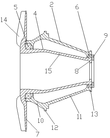
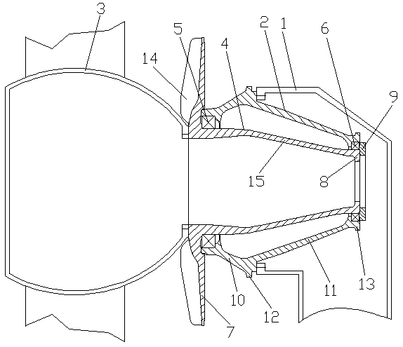
[0034] see figure 1 and figure 2, a megawatt-level low-speed direct-drive wind turbine shafting device, including a fixed shaft 2 coupled to the fixed end of the main frame 1 and a rotating shaft 4 coupled to the hub 3, the rotating shaft 4 is located inside the fixed shaft 2 An upwind bearing 5 and a downwind bearing 6 for supporting the rotation of the rotating shaft 4 are arranged between the fixed shaft 2 and the rotating shaft 4, the upwind bearing 5 is located on the hub 3 side, and the downwind bearing 6 is located on the main frame 1- On the side, the cross sections of the fixed shaft 2 and the rotating shaft 4 are tapered, and the section bending strength on the tapered surface 15 of the rotating shaft is equal. One end of the rotating shaft 4 is provided with a large flange 7, and the other end of the rotating shaft 4 is provided with There is a rotating shaft reinforced flange 8, the large flange 7 is located on the side of the upwind bearing 5, the rotating shaft...

Embodiment 2

[0037] see figure 1 and figure 2 , a megawatt-level low-speed direct-drive wind turbine shafting device, including a fixed shaft 2 coupled to the fixed end of the main frame 1 and a rotating shaft 4 coupled to the hub 3, the rotating shaft 4 is located inside the fixed shaft 2 An upwind bearing 5 and a downwind bearing 6 for supporting the rotation of the rotating shaft 4 are arranged between the fixed shaft 2 and the rotating shaft 4, the upwind bearing 5 is located on the hub 3 side, and the downwind bearing 6 is located on the main frame 1- On the side, the cross sections of the fixed shaft 2 and the rotating shaft 4 are tapered, and the section bending strength on the tapered surface 15 of the rotating shaft is equal. One end of the rotating shaft 4 is provided with a large flange 7, and the other end of the rotating shaft 4 is provided with There is a rotating shaft reinforced flange 8, the large flange 7 is located on the side of the upwind bearing 5, the rotating shaf...

Embodiment 3

[0043] see figure 1 and figure 2 , a megawatt-level low-speed direct-drive wind turbine shafting device, including a fixed shaft 2 coupled to the fixed end of the main frame 1 and a rotating shaft 4 coupled to the hub 3, the rotating shaft 4 is located inside the fixed shaft 2 An upwind bearing 5 and a downwind bearing 6 for supporting the rotation of the rotating shaft 4 are arranged between the fixed shaft 2 and the rotating shaft 4, the upwind bearing 5 is located on the hub 3 side, and the downwind bearing 6 is located on the main frame 1- On the side, the cross sections of the fixed shaft 2 and the rotating shaft 4 are tapered, and the section bending strength on the tapered surface 15 of the rotating shaft is equal. One end of the rotating shaft 4 is provided with a large flange 7, and the other end of the rotating shaft 4 is provided with There is a rotating shaft reinforced flange 8, the large flange 7 is located on the side of the upwind bearing 5, the rotating shaf...


PUM


Abstract

The invention discloses a megawatt level low speed direct-driven wind turbine generator shaft system device, and belongs to the technical field of wind driven generators. The megawatt level low speeddirect-driven wind turbine generator shaft system device comprises a fixed shaft and a rotary shaft, and is characterized in that an upwind bearing and a downwind bearing are arranged between the fixed shaft and the rotary shaft, cross sections of the fixed shaft and the rotary shaft are in a taper shape, a large flange plate is arranged at one end of the rotary shaft, a rotary shaft reinforcementflange plate is arranged at the other end of the rotary shaft, a bearing pressure ring is fixed on the rotary shaft reinforcement flange plate, the cross section of the fixed shaft is of a two-section type gradual change structure, a part, located between the upwind bearing and a fixed end of a main machine frame, of the fixed shaft, forms a fixed shaft taper face 1, and the other part, located between the downwind bearing and the fixed end of the main machine frame, of the fixed shaft, forms a fixed shaft taper face 2. The megawatt level low speed direct-driven wind turbine generator shaft system device is uniform in stress distribution under a large load condition, enables the shafts to be small in deformation, can inhibit deformation of air gaps well, reduces the designed size of the air gaps, improves a power factor of an electric generator, and then improves overall performance of the electric generator and a generator set, reduces overall weight and production cost of the electric generator, and has the characteristics of being good in rigidity and low in weight.

Description

technical field [0001] The invention relates to the technical field of wind power generators, in particular to a shafting device of a megawatt-level low-speed direct-drive wind power generator. Background technique [0002] With the development of the wind turbine market, low-speed direct-drive wind turbines have developed rapidly, and the market demand for large-MW low-speed direct-drive wind turbines is increasing. 6MW, 8MW and even 10MW have been launched on the market. low-speed direct-drive wind turbines. However, as the power increases, the blades become longer and the load increases significantly. The original traditional single-bearing shafting structure can no longer meet the structural design requirements. Therefore, the double-bearing shafting structure has begun to be used on large wind turbines. [0003] Due to the large bearing span of the double-bearing shafting structure, the axial dimension of the shaft is very long, and the deformation of the shaft will be...

Claims


Application Information

Patent Timeline
IPC IPC(8): F03D80/00F03D80/70F16C3/02F16H57/00
CPCF05B2240/60F16C3/02F16C2360/31F16H57/0037F03D80/00F03D80/70Y02E10/72Y02P70/50
Inventor 李源常巍斌蒋小平段志强常文娟汪波王慧勇
Owner DONGFANG ELECTRIC MACHINERY
Why Eureka
Try Eureka