Velocity ambiguity resolution angle measurement method for vehicle-mounted LFMCW radar

A technology for speed and angle measurement, applied in the field of signal processing, can solve the problems of reducing radar data rate and increasing signal processing time, and achieve the effect of reducing signal processing time and increasing radar data rate

Active Publication Date: 2019-11-22
UNIV OF ELECTRONIC SCI & TECH OF CHINA
View PDF5 Cites 18 Cited by
  • Summary
  • Abstract
  • Description
  • Claims
  • Application Information

AI Technical Summary

Problems solved by technology

This increases the signal processing

Method used


Image

  • Velocity ambiguity resolution angle measurement method for vehicle-mounted LFMCW radar
  • Velocity ambiguity resolution angle measurement method for vehicle-mounted LFMCW radar
  • Velocity ambiguity resolution angle measurement method for vehicle-mounted LFMCW radar

Examples


Embodiment 1

[0027] Step 1: Assume two targets, target 1 is in the direction of 28 degrees in front of the right of the radar (the left side of the radar is negative, and the right side is positive), the distance is 80m, and the speed is 30m / s; target 2 is in the direction of 23 degrees in front of the left side of the radar , the distance is 60m, and the speed is 13m / s. Set the test indicators: the absolute error of the target distance is within 1m, the absolute error of the speed is within 0.1m / s, and the absolute error of the angle is within 1 degree.

[0028] Step 2: Set the left and right cutoff frequencies of the eight low-pass filters LPF to -255MHz and 255MHz respectively, and the passband to 502MHz. Set the sampling rate (for a single ramp) of the 8 ADCs to 25.1MHz.

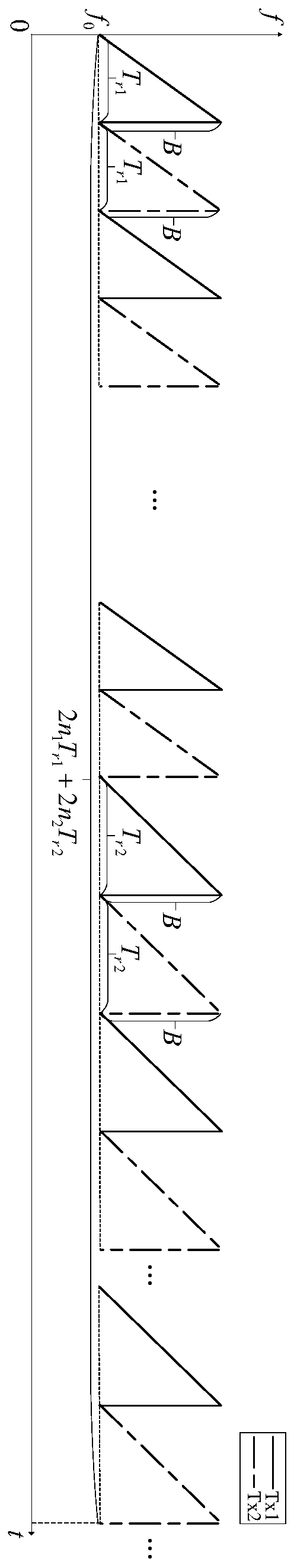
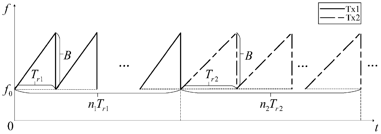
[0029] Step 3: Use the ramp generator to generate 2-channel linear FM continuous wave signals. Signal 1 T r1 is 40μs, bandwidth B is 500MHz, n 1 is 320; T of signal 2 r2 is 50μs, bandwidth B is 500MHz, n 2 for ...

Embodiment 2

[0033] Step 1: Assume two targets, target 1 is in the direction of 28 degrees in front of the right of the radar (the left side of the radar is negative, and the right side is positive), the distance is 80m, and the speed is 30m / s; target 2 is in the direction of 23 degrees in front of the left side of the radar , the distance is 60m, and the speed is 13m / s. Set the test indicators: the absolute error of the target distance is within 1m, the absolute error of the speed is within 0.1m / s, and the absolute error of the angle is within 1 degree.

[0034] Step 2: Set the left and right cutoff frequencies of the eight low-pass filters LPF to -205MHz and 205MHz respectively, and the passband to 402MHz. Set the sampling rate (for a single ramp) of the eight analog-to-digital converters ADC to 40MHz.

[0035] Step 3: Use the ramp generator to generate 2-channel linear FM continuous wave signals. Signal 1 T r1 20μs, bandwidth B is 400MHz, n 1 is 640; T of signal 2 r2 25μs, bandwidth ...

Embodiment 3

[0039] Step 1: Assume two targets, target 1 is in the direction of 28 degrees in front of the right of the radar (the left side of the radar is negative, and the right side is positive), the distance is 80m, and the speed is 30m / s; target 2 is in the direction of 23 degrees in front of the left side of the radar , the distance is 60m, and the speed is 13m / s. Set the test indicators: the absolute error of the target distance is within 1m, the absolute error of the speed is within 0.1m / s, and the absolute error of the angle is within 1 degree.

[0040] Step 2: Set the left and right cutoff frequencies of the eight low-pass filters LPF to -155MHz and 155MHz respectively, and the passband to 302MHz. Set the sampling rate (for a single ramp) of the 8 ADCs to 37.5MHz.

[0041] Step 3: Use the ramp generator to generate 2-channel linear FM continuous wave signals. Signal 1 T r1 16μs, bandwidth B is 300MHz, n 1 is 800; T of signal 2 r2 is 32μs, bandwidth B is 300MHz, n 2 for 400...


PUM


Abstract

The invention discloses a velocity ambiguity resolution angle measurement method for vehicle-mounted LFMCW radar, belongs to the signal processing technology, and particularly relates to the velocityambiguity resolution and radar virtual aperture direction of arrival measurement technology. According to the invention, velocity ambiguity resolution and MIMO radar virtual aperture angle measurementprocessing are carried out in one frame of signal, a two-transmitting four-receiving radar system is taken as an example, a radar transmitting end transmits linear frequency modulation continuous wave signals with different slope durations and the same bandwidth by using a time division multiplexing technology, and a radar receiving end simultaneously receives signals reflected by two transmitting antennas through an object by using four receiving antennas. Echo signals are subjected to frequency mixing, low-pass filtering and analog-to-digital conversion and finally enter a digital signal processor DSP. 2D-FFT and two-dimensional constant false alarm detection are performed in the DSP, then resolution of velocity ambiguity and phase compensation are conducted, and finally MIMO radar virtual aperture angle measurement processing is carried out, thus realizing the purpose of the invention. The method has the effects of reducing the signal processing time and improving the radar data rate.

Description

technical field [0001] The invention belongs to the signal processing technology, and in particular relates to the speed fuzzy resolution technology and the MIMO radar virtual aperture measurement wave direction of arrival technology. Background technique [0002] 77G vehicle-mounted millimeter-wave radar is more and more applied to automotive driving assistance systems due to its advantages such as large bandwidth, short wavelength, high detection accuracy, and small size. The basic working process of the system radar is that the transmitter generates a fast ramp mode LFMCW waveform, that is, a high-frequency constant-amplitude continuous wave whose transmission frequency changes linearly with time, also known as a sawtooth wave. The target echo signal is mixed with the transmitted local oscillator signal, and then filtered, and the obtained beat baseband signal contains the distance, speed and angle information of the target, and the target can be measured by the beat base...

Claims


Application Information

Patent Timeline
IPC IPC(8): G01S13/58G01S7/282
CPCG01S13/584G01S7/282G01S2013/0254
Inventor 邹林黄述康童纵梁飞汪学刚钱璐
Owner UNIV OF ELECTRONIC SCI & TECH OF CHINA
Why Eureka
Try Eureka