

SiC power device driving circuit capable of suppressing bridge arm crosstalk and control method thereof
A driving circuit and power device technology, which is applied in the field of power electronics, can solve problems such as the small optional range of driving negative voltage, the inability to adjust the turn-off gate resistance, and the inability to adjust the turn-off speed of power devices, so as to achieve short drive circuits and lighten effect, the effect of small gate parasitic inductance
- Summary
- Abstract
- Description
- Claims
- Application Information
AI Technical Summary
Problems solved by technology
Method used
Image

Examples
Embodiment 1
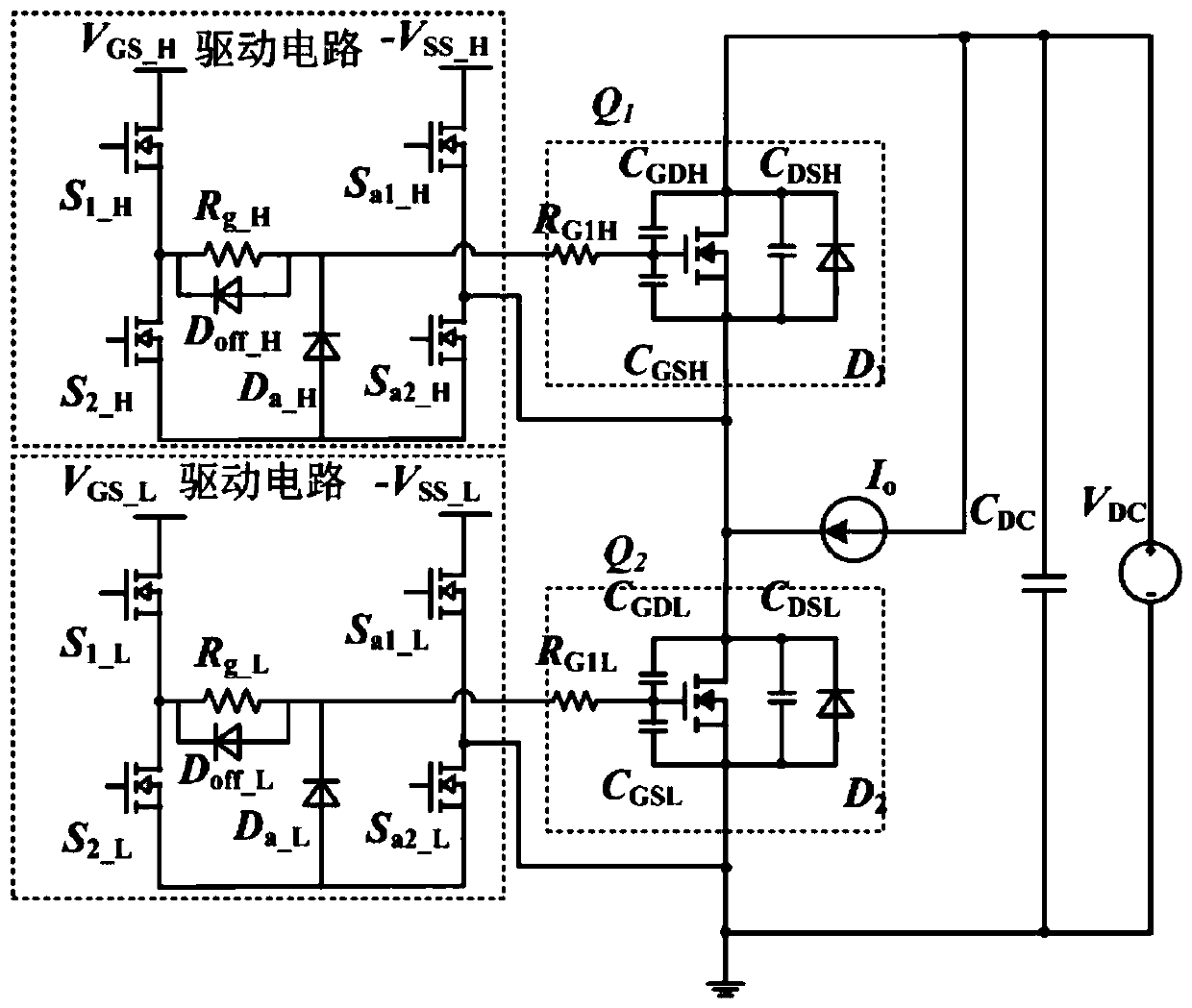
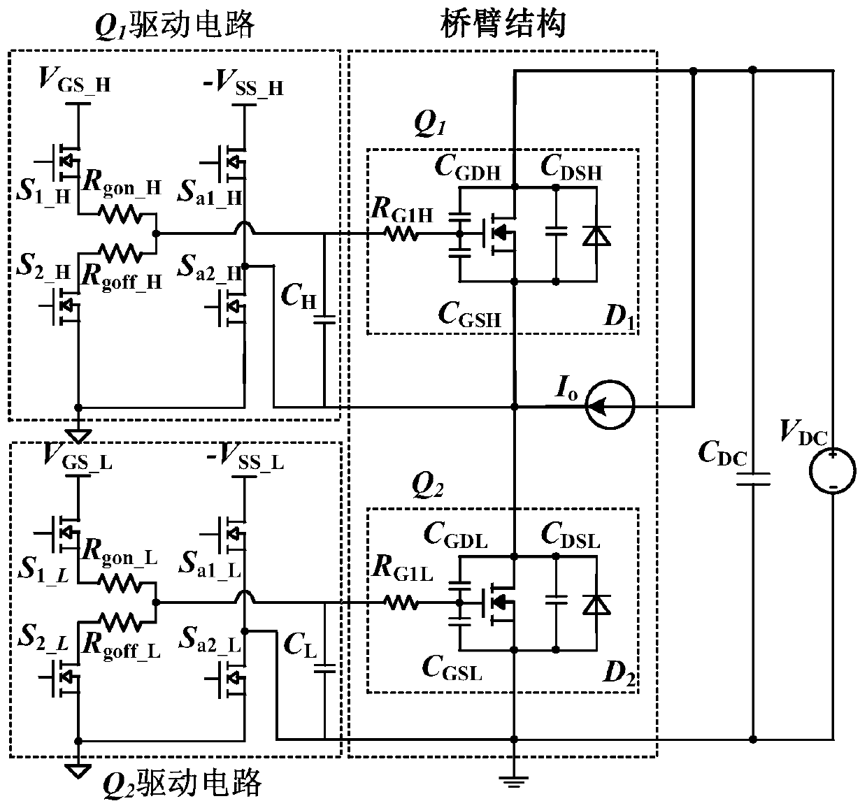
[0043] This embodiment provides a SiC power device drive circuit capable of suppressing bridge arm crosstalk, such as figure 2 As shown, the bridge arm includes the upper tube Q 1 and down tube Q 2 , upper tube Q 1 connect Q 1 drive circuit, lower tube Q 2 connect Q 2 Drive circuit. In the figure, the upper tube Q 1 The equivalent circuit includes the upper switch Q 1 The gate equivalent resistance R G1H , Gate-drain junction capacitance C GDH , Gate-source junction capacitance C GSH , Drain-source junction capacitance C DSH and the body diode D 1 . down tube Q 2 The equivalent circuit includes downside Q 2 The gate equivalent resistance R G1L , Gate-drain junction capacitance C GDL , Gate-source junction capacitance C GSL , Drain-source junction capacitance C DSL and the body diode D 2 .
[0044] The Q 1 The drive circuit includes an upper transistor G pole drive circuit, an upper transistor S pole driver circuit, and an upper capacitor C arranged betwee...
Embodiment 2
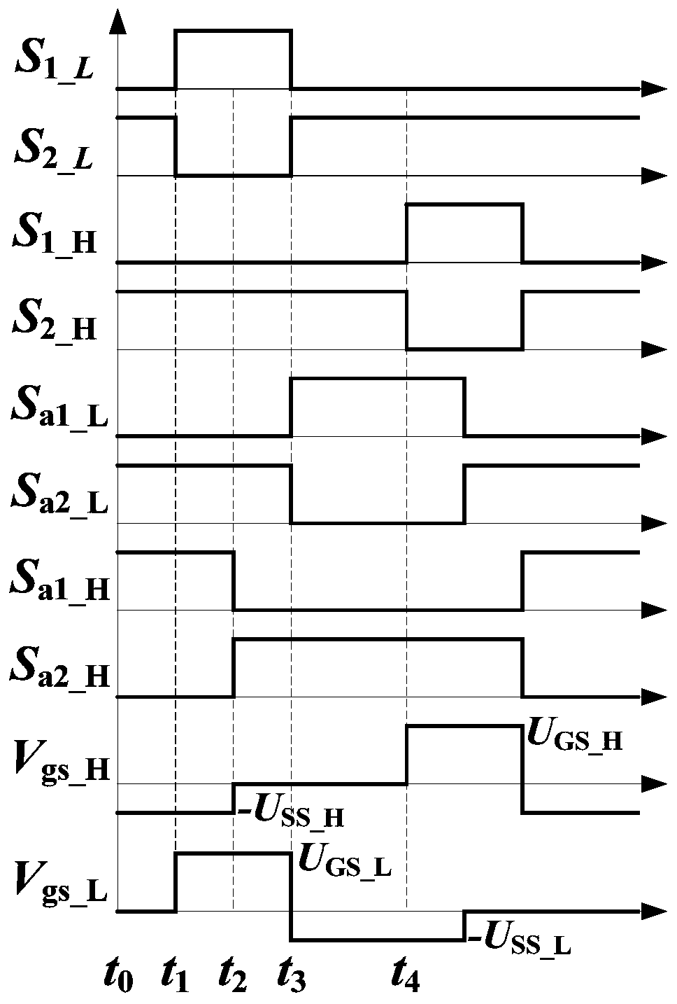
[0053] This embodiment provides a control method for a SiC power device drive circuit, which divides one cycle of the SiC power device drive circuit in Embodiment 1 into t 0 ~t 1 , t 1 ~t2 , t 2 ~t 3 , t 3 ~t 4 Four stages, down tube Q 2 Active tube, top tube Q 1 The control logic for passive management is as follows, and the specific control logic is as follows image 3 shown.
[0054] t 0 ~t 1 The first stage: the second lower tube G pole switch tube S 2_L and the second lower tube S pole switch tube S a2_L conduction, lower tube Q 2 The gate-source voltage of the gate is 0V, and it is in an off state at this time; the second upper tube G-electrode switch tube S 2_H and the first upper transistor S pole switch S a1_H conduction, the upper transistor Q 1 The gate-to-source voltage is -U ss_H , to prevent downpipe Q in the second stage 2 The moment of opening Q 1 Prepare for the gate-to-source forward voltage spike to exceed the threshold voltage;
[0055] t...
PUM
 Abstract
Description
Claims
Application Information