Eureka AIR delivers breakthrough ideas for toughest innovation challenges, trusted by R&D personnel around the world.

Novel actuator with two-stage amplification mechanism and that provides axial magnetic field with bar

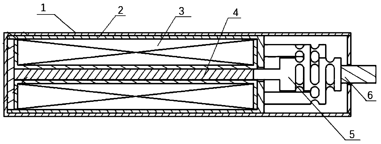
An axial magnetic field, two-stage amplification technology, applied in piezoelectric effect/electrostrictive or magnetostrictive motors, generators/motors, electrical components, etc., can solve the problem of large radial volume, large output displacement of the driver, There are many problems in the amplification mechanism, so as to achieve the effect of expanding the application environment, stable working state, and increasing output displacement.

Pending Publication Date: 2019-11-22
BAOTOU RES INST OF RARE EARTHS +1
View PDF3 Cites 3 Cited by
  • Summary
  • Abstract
  • Description
  • Claims
  • Application Information

AI Technical Summary

Problems solved by technology

However, there are some problems in this design: in order to ensure the symmetrical structure when the volume of the magnifying mechanism is constant, the effective horizontal structure for the magnification is only 1 / 2, and when the magnification is guaranteed, the overall horizontal structure is will double in size
The output displacement of the magnetostrictive rod is amplified by using the first to third level levers. Its radial volume is large, and because there are many parts in the amplification mechanism, the assembly complexity in the small-volume driver is relatively high, and it is difficult to realize. At the same time, it causes Its output accuracy and reliability decrease
[0008] With the continuous miniaturization of various precision devices, the requirements for the driver are also increasing. Although the existing method of placing the amplifier inside the driver can reduce the size of the driver, the volume of the amplifier part will still be large. Restricting its use, how to keep the size of the driver miniaturized while obtaining a large output displacement is still an unresolved problem

Method used


Image

  • Novel actuator with two-stage amplification mechanism and that provides axial magnetic field with bar
  • Novel actuator with two-stage amplification mechanism and that provides axial magnetic field with bar
  • Novel actuator with two-stage amplification mechanism and that provides axial magnetic field with bar

Examples


Embodiment 1

[0068] like Figure 8 Shown is a schematic structural view of Embodiment 1 of the present invention.

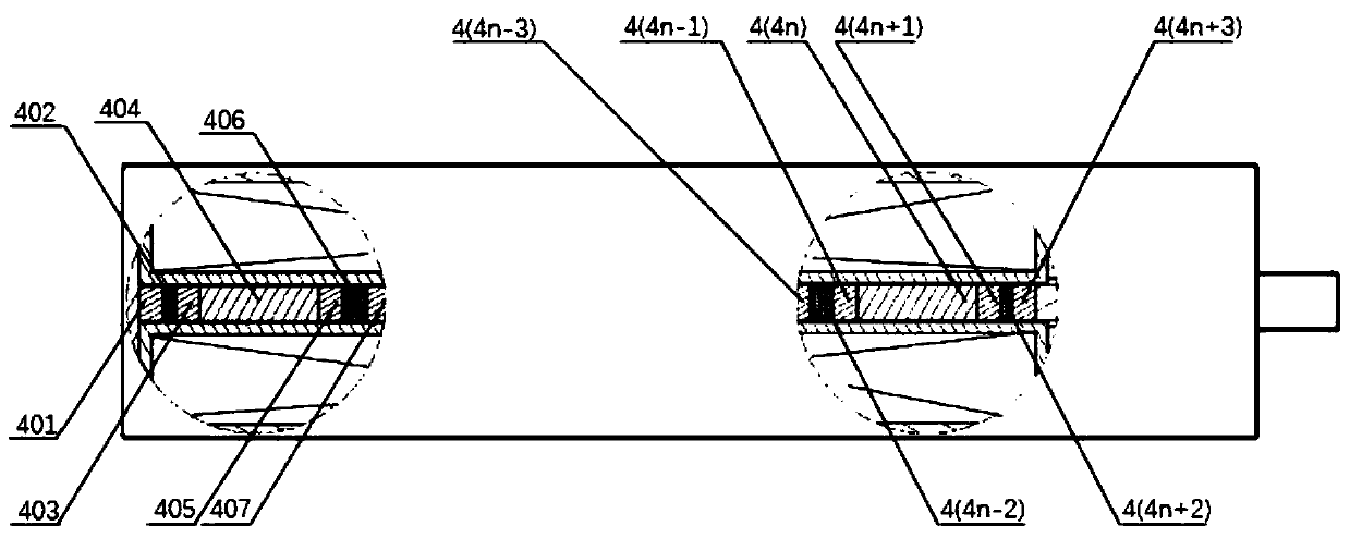
[0069] In the new type of actuator with a two-stage amplification mechanism provided by the rod material, the combination 4 includes two magnet units and a magnetostrictive rod unit, and the magnet unit is connected to both sides of the magnetostrictive rod unit . The magnetic conduction unit 401 is connected to the permanent magnet unit 402, the permanent magnet unit 402 is connected to the magnetic conduction unit 403, the magnetic conduction unit 403 is connected to the magnetostrictive rod 404, the magnetostrictive rod 404 is connected to the magnetic conduction unit 405, and the magnetic conduction unit 403 is connected to the magnetostrictive unit 404. The monomer 405 is connected to the permanent magnet monomer 406 , and the permanent magnet monomer 406 is connected to the magnetic conduction monomer 407 to form the assembly 4 .

[0070] The outside of the assembly 4...

Embodiment 2

[0072] like Figure 9 Shown is a schematic structural view of the combination 4 of Example 2 of the present invention.

[0073] The assembly 4 includes three magnet units and two magnetostrictive rod units.

[0074] The magnetic conduction unit 401 is connected to the permanent magnet unit 402, the permanent magnet unit 402 is connected to the magnetic conduction unit 403, the magnetic conduction unit 403 is connected to the magnetostrictive rod unit 404, and the magnetostrictive rod unit 404 is connected to the magnetic conduction unit 405, the magnetic conduction unit 405 is connected to the permanent magnet unit 406, the permanent magnet unit 406 is connected to the magnetic conduction unit 407, the magnetic conduction unit 407 is connected to the magnetostrictive rod unit 408, and the magnetostrictive rod unit 408 is connected to the magnetic conduction unit The single body 409 , the magnetic conductive single body 409 is connected with the permanent magnetic single body ...

Embodiment 3

[0076] like Figure 10 Shown is a schematic structural view of the combination 4 of Example 3 in the present invention.

[0077] The assembly 4 includes five magnet units and four magnetostrictive rod units.

[0078] The magnetic conduction unit 401 is connected to the permanent magnet unit 402, the permanent magnet unit 402 is connected to the magnetic conduction unit 403, the magnetic conduction unit 403 is connected to the magnetostrictive rod unit 404, and the magnetostrictive rod unit 404 is connected to the magnetic conduction unit 405, the magnetic conduction unit 405 is connected to the permanent magnet unit 406, the permanent magnet unit 406 is connected to the magnetic conduction unit 407, the magnetic conduction unit 407 is connected to the magnetostrictive rod unit 408, and the magnetostrictive rod unit 408 is connected to the magnetic conduction unit Monomer 409, the magnetic conductor monomer 409 is connected to the permanent magnet monomer 410, the permanent ma...


PUM


Abstract

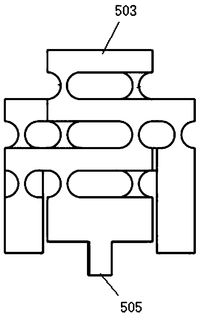
The invention discloses a novel actuator provided with a two-stage amplification mechanism and that provides an axial magnetic field with bars. The novel actuator comprises a non-magnetic-conductive shell, a magnetic-conductive frame, a magnet exciting coil, a combined body, the two-stage micro-displacement amplification mechanism and an output rod. The magnet exciting coil is sleeved outside thecombined body and is placed in the magnetic conductive frame, and the magnetic conductive frame and the combined body form a closed magnetic circuit; the magnetic conductive frame is arranged in the non-magnetic conductive shell; one end of the combined body is connected with the magnetic conductive frame, the other end of the combined body is connected with the input end of the two-stage micro-displacement amplification mechanism; the combined body is used for transmitting displacement to the two-stage micro-displacement amplification mechanism, the fixed end of the two-stage micro-displacement amplification mechanism is connected to the magnetic conductive frame, the output end of the two-stage micro-displacement amplification mechanism is connected with the rear end of the output rod, and the front end of the output rod extends out of the non-magnetic shell; the two-stage micro-displacement amplification mechanism amplifies the displacement of the combined body and transmits theamplified displacement to the output rod; and the output rod is used for outputting the displacement. The output displacement of a driver is increased, and the size of the driver is reduced.

Description

technical field [0001] The invention relates to a precision control technology, in particular to a novel actuator with a two-stage amplifying mechanism that a bar provides an axial magnetic field. Background technique [0002] In recent years, various drivers with high resolution and fast response have been widely used in various fields such as microelectronics, nanotechnology, biomedical engineering, and precision machining. With the continuous development of technology, higher requirements are put forward for various indicators of the driver. Giant magnetostrictive materials have a series of excellent characteristics such as large strain value, high response speed, high energy density, large electromechanical coupling coefficient, high reliability, etc., and show good application prospects in the field of actuators. [0003] For some environments that require a lower output range, such as below 100μm, or some environments that have no limitation on the volume of the drive...

Claims


Application Information

Patent Timeline
Patent Type & Authority Applications(China)
IPC IPC(8): H02N2/02H02N2/04
CPCH02N2/02H02N2/043
Inventor 郝宏波乔禹田若楠王婷婷梁雨萍张光睿
Owner BAOTOU RES INST OF RARE EARTHS
Why Eureka
Eureka Blog
Learn More