
Visible light positioning method based on aperture receiver and weighted centroid positioning method

A weighted center of mass and positioning method technology, which is applied in the direction of location information-based services, specific environment-based services, positioning, etc., can solve the problem of equipment complexity and high complexity of positioning algorithms, and achieve the advantages of equipment miniaturization, easy implementation, The effect of improving positioning accuracy

Active Publication Date: 2020-07-03
SUN YAT SEN UNIV
View PDF8 Cites 0 Cited by
  • Summary
  • Abstract
  • Description
  • Claims
  • Application Information

AI Technical Summary

Problems solved by technology

[0008] In order to overcome the defects of equipment complexity and positioning algorithm complexity in the prior art, the present invention proposes a new aperture receiver structure and AOA and WCL joint positioning algorithm for the new aperture receiver structure

Method used


Image

  • Visible light positioning method based on aperture receiver and weighted centroid positioning method
  • Visible light positioning method based on aperture receiver and weighted centroid positioning method
  • Visible light positioning method based on aperture receiver and weighted centroid positioning method

Examples


Embodiment 1

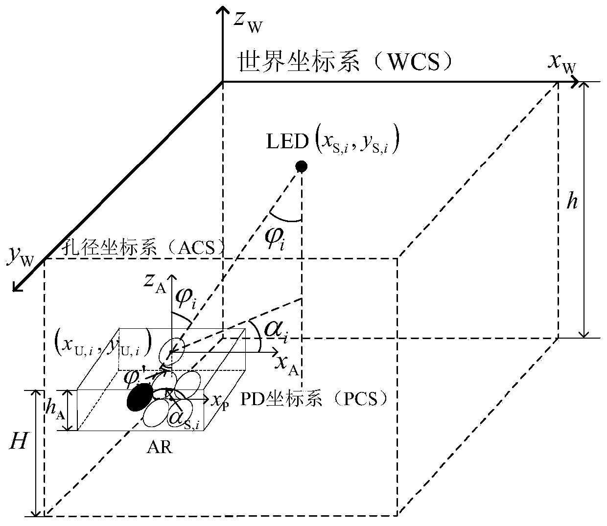
[0052] For ease of expression, the present invention defines the following two coordinate systems:

[0053] The plane where the aperture is located is defined as the aperture coordinate system (Aperture Coordinate System, ACS);

[0054] The indoor space where the aperture receiver is located is defined as a world coordinate system (World Coordinate System, WCS).

[0055] Assuming that a total of I is deployed in the room A LED lamps, where the coordinates of the i (i=1,2,...,I) LED lamps are (x S,i ,y S,i ), and all LED lamps satisfy the Lambertian radiation model with the Lambert coefficient m. When considering the VLP positioning scenario using only one LED light, I A =1. For large-scale indoor positioning scenarios where a large number of LED lamps are deployed, the cell frequency reuse mechanism of the cellular network can be referred to, and lamps with suitable lampshade structures can be selected to control signal coverage and interference range. Based on this cons...

Embodiment 2

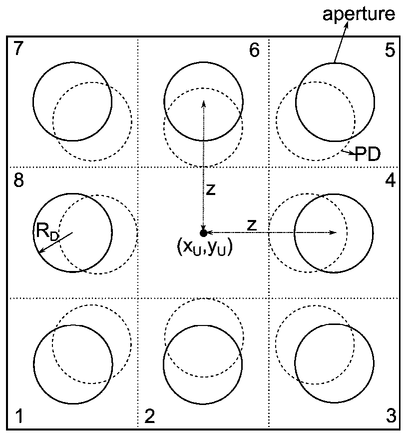
[0086] On the basis of Embodiment 1, in an actual system, apertures and / or photodiodes with different surface shapes can be selected according to specific requirements and conditions. At this time, the basic processing flow of the present invention is still applicable, but the center of the photodiode and the The specific expression of the relative position relationship of the aperture center and the calculation formula of the overlapping area between the photodiode and the light spot are adjusted and changed to adapt to the specific surface shape of the adapter. For ease of illustration, it is assumed in this embodiment that both the aperture and the photodiode are circular.

[0087] According to the steps 1)-3) described in the summary of the invention, I can be obtained D LED-ID. Suppose it is known that the i-th LED-ID is (x S,i ,y S,i ), the following describes how to implement the specific process of solving the terminal position (that is, the coordinates of the cente...


PUM


Abstract

The invention relates to a visible light positioning method based on an aperture receiver and a weighted centroid positioning method, and provides a novel aperture receiver structure and an AOA and WCL combined positioning algorithm for the novel aperture receiver structure. According to the structure and the positioning algorithm, accurate positioning can be achieved only through a single LED lamp, and compared with a traditional VLP method, the structure and the positioning algorithm have the advantages of being simple, easy to achieve, high in positioning precision and the like. And if a plurality of LED lamps are adopted, the system can further improve the positioning precision and provide better system performance.

Description

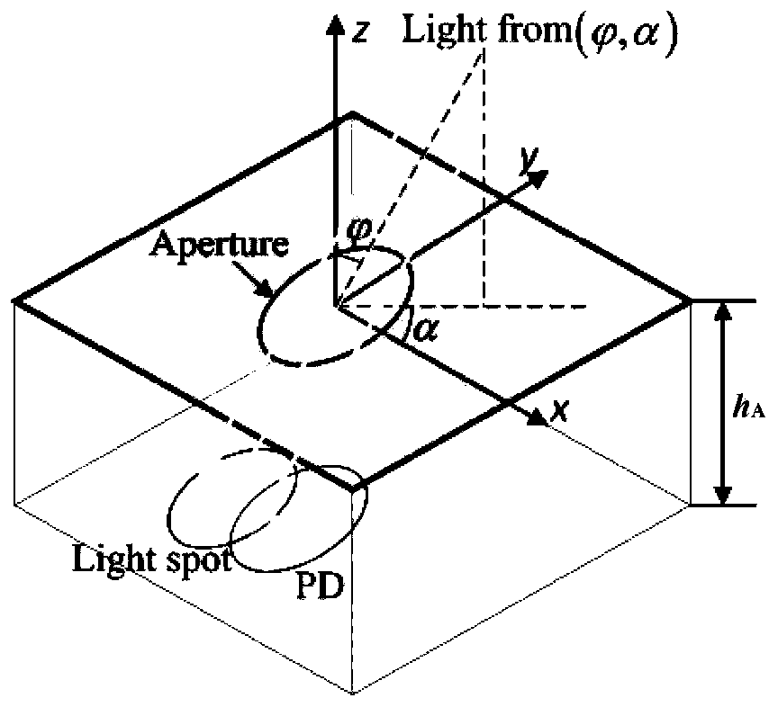
technical field [0001] The present invention relates to the technical field of visible light positioning, and more particularly, to a visible light positioning method based on an aperture receiver (Aperture Receiver, AR) and a weighted centroid localization method (Weighted Centroid Localization, WCL). Background technique [0002] The aperture receiver structure was first proposed in 2015 [1] , is a new visible light receiver structure with good directivity. Through a specific aperture structure design, it can well control the path and direction of light reaching the optoelectronic device, so as to obtain better angle diversity gain. [0003] The aperture receiver is composed of multiple receiving elements (Receiving Elements, RE), and each receiving element is composed of an aperture (Aperture, AP) and a PD (Photodiode, photodiode). Layer plane, the vertical distance between two planes is h A . figure 1 A schematic diagram of the aperture receiver composed of a circul...

Claims


Application Information

Patent Timeline
Patent Type & Authority Patents(China)
IPC IPC(8): H04W64/00H04W4/02H04W4/33G01S5/16H04B10/60
CPCG01S5/16H04B10/60H04W4/023H04W4/33H04W64/006
Inventor 江明彭时玉
Owner SUN YAT SEN UNIV
Learn More