External rotor chassis dynamometer for direct drive of permanent magnet synchronous motor

A technology of permanent magnet synchronous motor and chassis dynamometer, which is applied in the testing of machine/structural components, vehicle testing, power measurement, etc., and can solve the problem of large floor area of ​​dynamometer, many mechanical transmission links, and failure rate. Advanced problems, to achieve the effect of reducing mechanical transmission links, compact structure, and fast response

Pending Publication Date: 2019-11-26
洛阳合能电气有限公司
View PDF0 Cites 7 Cited by
  • Summary
  • Abstract
  • Description
  • Claims
  • Application Information

AI Technical Summary

Problems solved by technology

[0004] In view of this, the purpose of the present invention is to overcome the deficiencies of the prior art and provide an outer rotor chassis dynamometer directly driven by a permanent magnet synchronous motor to solve the problem of the large footprint of the dynamometer in the prior art and the mechanical transmission link. Many, low efficiency, high failure rate technical problems

Method used


Image

  • External rotor chassis dynamometer for direct drive of permanent magnet synchronous motor
  • External rotor chassis dynamometer for direct drive of permanent magnet synchronous motor
  • External rotor chassis dynamometer for direct drive of permanent magnet synchronous motor

Examples


Embodiment 1

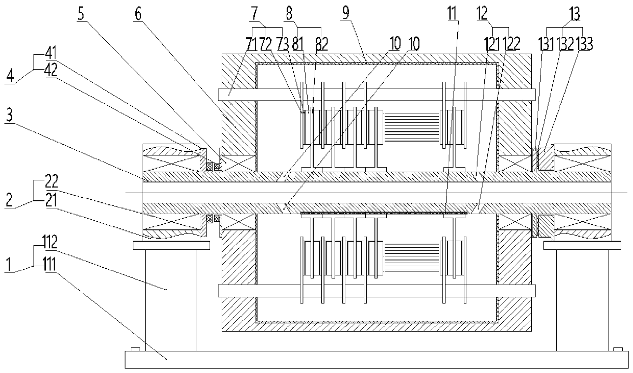
[0033] like figure 1 As shown, an outer rotor chassis dynamometer directly driven by a permanent magnet synchronous motor includes a base 1 , a bearing unit 2 , a main shaft 3 , an encoder 4 , a first bearing 5 , a rotating hub 6 and a torque measurer 13 . The base 1 includes a bottom plate 111 and support columns 112 disposed on both sides of the bottom plate 111 . The main shaft 3 is fixedly installed between the support columns 112 through the bearing unit 2 . The bearing unit 2 includes a bearing seat 21 and a second bearing 22 . The rotating hub 6 is mounted on the main shaft 3 through the first bearing 5, and the rotating hub 6 is provided with electromagnetic resistance by a permanent magnet synchronous motor to simulate the mechanical inertia. The permanent magnet synchronous motor includes a rotor assembly 7 and a stator assembly 8 . The stator assembly 8 is fixedly mounted on the main shaft 3 to provide a rotating resistance magnetic field for the rotor assembly ...

Embodiment 2

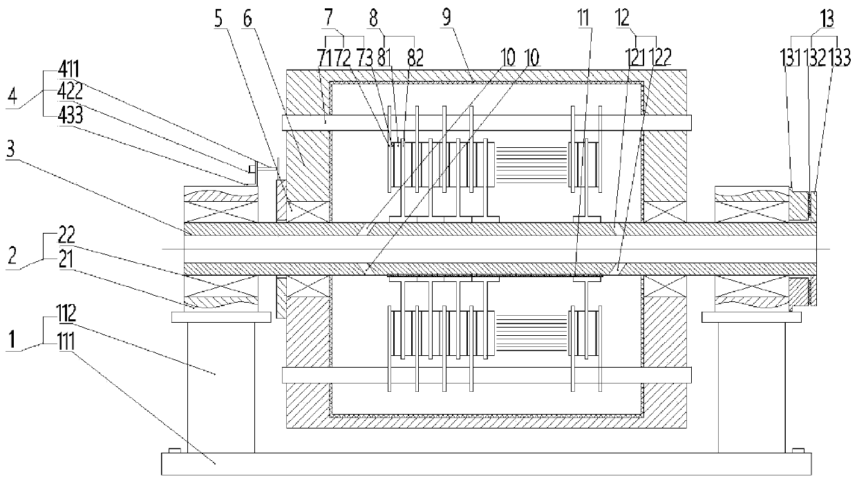
[0037] like figure 2 As shown, an outer rotor chassis dynamometer directly driven by a permanent magnet synchronous motor includes a base 1 , a bearing unit 2 , a main shaft 3 , an encoder 4 , a first bearing 5 , a hub 6 and a torque measuring device 13 . The base 1 includes a bottom plate 111 and support columns 112 disposed on two sides of the bottom plate 111 . The main shaft 3 is fixedly installed between the support columns 112 through the bearing unit 2 . The bearing unit 2 includes a bearing seat 21 and a second bearing 22 . The rotating hub 6 is installed on the main shaft 3 through the first bearing 5, and the rotating hub 6 is provided with electromagnetic resistance by a permanent magnet synchronous motor to simulate mechanical inertia. The permanent magnet synchronous motor includes a rotor assembly 7 and a stator assembly 8 . The stator assembly 8 is fixedly installed on the main shaft 3 and provides a rotating resistance magnetic field for the rotor assembly ...

Embodiment 3

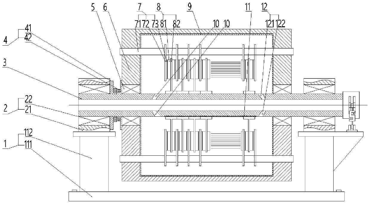
[0041] like image 3 , Figure 4 As shown, an outer rotor chassis dynamometer directly driven by a permanent magnet synchronous motor includes a base 1 , a bearing unit 2 , a main shaft 3 , an encoder 4 , a first bearing 5 , a hub 6 and a torque measuring device 13 . The base 1 includes a bottom plate 111 and support columns 112 disposed on two sides of the bottom plate 111 . The main shaft 3 is fixedly installed between the support columns 112 through the bearing unit 2 . The bearing unit 2 includes a bearing seat 21 and a second bearing 22 . The rotating hub 6 is installed on the main shaft 3 through the first bearing 5, and the rotating hub 6 is provided with electromagnetic resistance by a permanent magnet synchronous motor to simulate mechanical inertia. The permanent magnet synchronous motor includes a rotor assembly 7 and a stator assembly 8 . The stator assembly 8 is fixedly installed on the main shaft 3 and provides a rotating resistance magnetic field for the rot...


PUM


Abstract

The invention discloses an external rotor chassis dynamometer for the direct drive of a permanent magnet synchronous motor, which relates to the technical field of detection equipment for automobilesand engineering vehicles. The technical problems of large floor space, many mechanical transmission links, low efficiency and high failure rate of a dynamometer in the prior art are solved. The external rotor chassis dynamometer for the direct drive of the permanent magnet synchronous motor comprises a base, a main shaft, an encoder, a torque measuring device and a rotating hub. The main shaft isfixedly mounted on the base through a bearing unit. The rotating hub is mounted on the main shaft through a first bearing. The rotating hub is provided with resistance by the permanent magnet synchronous motor. The permanent magnet synchronous motor comprises a stator assembly and a rotor assembly. The stator assembly is fixedly mounted on the main shaft. The rotor assembly is fixedly mounted on the rotating hub. According to the invention, the rotor assembly is integrated with the rotating hub, so as to directly drive the rotating hub to rotate; the stator assembly is fixedly arranged insidethe motor; the external rotor chassis dynamometer has the advantages of compact structure, reduced floor space, reduced mechanical transmission links, improved efficiency and reduced failure rate.

Description

technical field [0001] The invention relates to the technical field of detection equipment for automobiles and engineering vehicles, in particular to an outer rotor chassis dynamometer directly driven by a permanent magnet synchronous motor. Background technique [0002] Chassis dynamometer is an indoor bench test equipment used to test the performance of automobiles and engineering vehicles, such as power performance, multi-condition emission index, fuel index, pure electric cruising range, etc. The chassis dynamometer simulates the road surface through the roller, and calculates Road simulation equation, and use the loading device to simulate, to achieve accurate simulation of various working conditions of automobiles and engineering vehicles, it can be used for loading and debugging of automobiles and engineering vehicles, and diagnose the faults of vehicles under load conditions; the chassis dynamometer is easy to use , reliable performance, not affected by external cond...

Claims


Application Information

Patent Timeline
Patent Type & Authority Applications(China)
IPC IPC(8): G01M17/007G01L3/24
CPCG01L3/24G01M17/007
Inventor 张华平
Owner 洛阳合能电气有限公司
Why Eureka
Try Eureka