Speed-adjustable magnetic coupler of guiding rail sliding block type

A technology of magnetic coupler and linear guide slider, applied in the direction of permanent magnet clutch/brake, electric brake/clutch, electrical components, etc., can solve the problems of uneven thickness of air gap, affecting transmission efficiency, large magnetic leakage, etc. To achieve the effect of compact structure, stable transmission and reduced demand

Active Publication Date: 2019-11-26
JIANGSU UNIV
View PDF6 Cites 0 Cited by
  • Summary
  • Abstract
  • Description
  • Claims
  • Application Information

AI Technical Summary

Problems solved by technology

But this invention adopts slider rocker to control each permanent magnet to swing, thereby causes the thickness of the air gap between the permanent magnet disc and the conductor disc to be uneven, makes the intervals of each permanent magnet on the permanent disc larger, and forms a larger flux leakage, which affects transmission efficiency

Method used


Image

  • Speed-adjustable magnetic coupler of guiding rail sliding block type
  • Speed-adjustable magnetic coupler of guiding rail sliding block type
  • Speed-adjustable magnetic coupler of guiding rail sliding block type

Examples


Embodiment 1

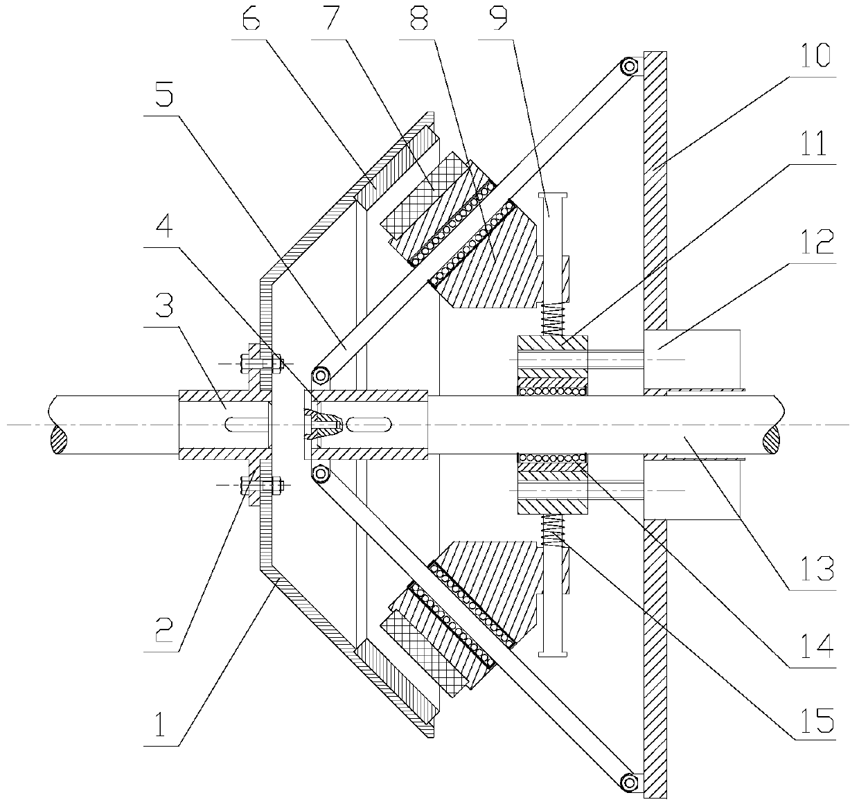
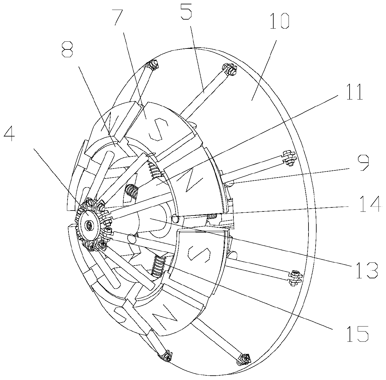
[0027] Such as figure 1 As shown, a guide rail slider type adjustable speed magnetic coupler includes a conductor frustum-shaped disk assembly and a permanent magnet conical disk assembly, wherein the speed regulating device is installed on the permanent magnet conical disk assembly, and the conductor frustum-shaped disk assembly The assembly includes a conductor ring 6, a driven base plate 1, a driven shaft 3 and a driven shaft sleeve 2, the right end of the driven shaft 3 is connected to the driven shaft sleeve 2 through a key, and the driven shaft sleeve 2 is connected to the driven shaft sleeve 2. The base discs 1 are fixed together by bolts, and the conductor ring 6 is installed on the inner surface of the driven base disc 1 to form a conductor frustum-shaped disc.

[0028] The permanent magnet tapered disk assembly includes a permanent magnet 7, a ball type linear guide rail slider 8, a guide rail 5, a fixed plate 10, a screw motor 12, a sleeve 11, a sliding rod 9, a com...

Embodiment 2

[0032] The speed regulation principle of this embodiment is basically the same as that of Embodiment 1. The difference in structure is that the solid conductor ring of the conductor ring 6 in the conductor frustum-shaped disk assembly is replaced by a cage-type conductor ring, and the cage-type conductor ring is composed of conductor copper disks 17 and The yoke iron plate 16 is composed of, such as Figure 6 shown. The surface of conductor copper plate 17 is processed with a number of rectangular grooves, and the surface of yoke iron plate 16 is processed with small bumps with the same shape as the rectangular grooves. The fan-shaped grooves and small bumps are interference fit, and after the fit, a cage-shaped conductor ring is formed and embedded in the driven substrate. The conductor ring is fixed on the driven base plate 1 by means of screw connection, riveting or welding. The difference in the working principle is that the motor drives the permanent magnet conical disk ...


PUM


Abstract

The invention relates to the technical field of transmission in mechanical engineering, and particularly to a speed-adjustable magnetic coupler of a guiding rail sliding block type. The coupler is formed by a conductor round-platform-shape disc assembly and a permanent-magnet cone-shape disc assembly. A speed adjustment device is mounted on the permanent-magnet cone-shape disc assembly. A driven disc is mounted at an inner surface of a driven base body disc by conductor rings to form a conductor round-platform-shape disc assembly. Driving discs are respectively fixed on outer surfaces of ball-type straight-line guiding rail sliding blocks by permanent magnets in a manner of alternate arrangement of N and S poles to form the permanent-magnet cone-shape disc assembly. Silk poles are driven through motors to rotate, sleeve barrels and straight-line bearings are enabled to move in an axial direction of a driving shaft, sliding rods and compression springs fixed on the sleeve barrels push the sliding blocks, the ball-type straight-line guiding rail sliding blocks are enabled to slide along straight-line guiding rails, then direct facing areas between the permanent magnets and the conductor rings are enabled to change simultaneously in circumferential directions and guiding rail sliding directions, and thus highly efficient speed adjustment is realized.

Description

technical field [0001] The invention relates to the technical field of transmission in mechanical engineering, and relates to a non-contact connected magnetic induction coupler, in particular to a guide rail slider type adjustable speed magnetic coupler. It can be used as a device for power transmission and speed regulation in fan and pump loads. Background technique [0002] Magnetic couplings transmit force and motion using a magnetic field generated by permanent magnets. In certain occasions, the speed-regulating magnetic coupler is superior to the frequency converter and the hydraulic coupler for the electric drive system of fans and pumps. The advantages of the magnetic coupler are: (1) The motor and the load realize non-contact transmission. Even the vibration caused by the motor itself will not cause the load vibration, so that the vibration problem of the entire system is effectively reduced, and the failure rate of the system is greatly reduced. It will not cause ...

Claims


Application Information

Patent Timeline
Patent Type & Authority Applications(China)
IPC IPC(8): H02K49/10
CPCH02K49/104
Inventor 杨超君陈子清吴俊孙佳杰彭志卓朱莉邰蒋西
Owner JIANGSU UNIV
Why Eureka
Try Eureka