
Burners control method and device for each furnace section of soaking pit

A control method and technology of soaking furnace, which are used in heat treatment process control, heat treatment furnaces, furnaces, etc., can solve the problems of unstable combustion conditions of burners, low gas flow, and low furnace temperature.

Active Publication Date: 2019-11-29
武汉钢铁有限公司
View PDF11 Cites 2 Cited by
  • Summary
  • Abstract
  • Description
  • Claims
  • Application Information

AI Technical Summary

Problems solved by technology

[0003] However, when the exit temperature of the slab in the existing soaking furnace is low, for example, when it is lower than 1120°C, the overall heat load needs to be reduced. The gas flow rate is low, resulting in unstable combustion of the burner, and even flameout

Method used


Image

  • Burners control method and device for each furnace section of soaking pit
  • Burners control method and device for each furnace section of soaking pit
  • Burners control method and device for each furnace section of soaking pit

Examples


Embodiment 1

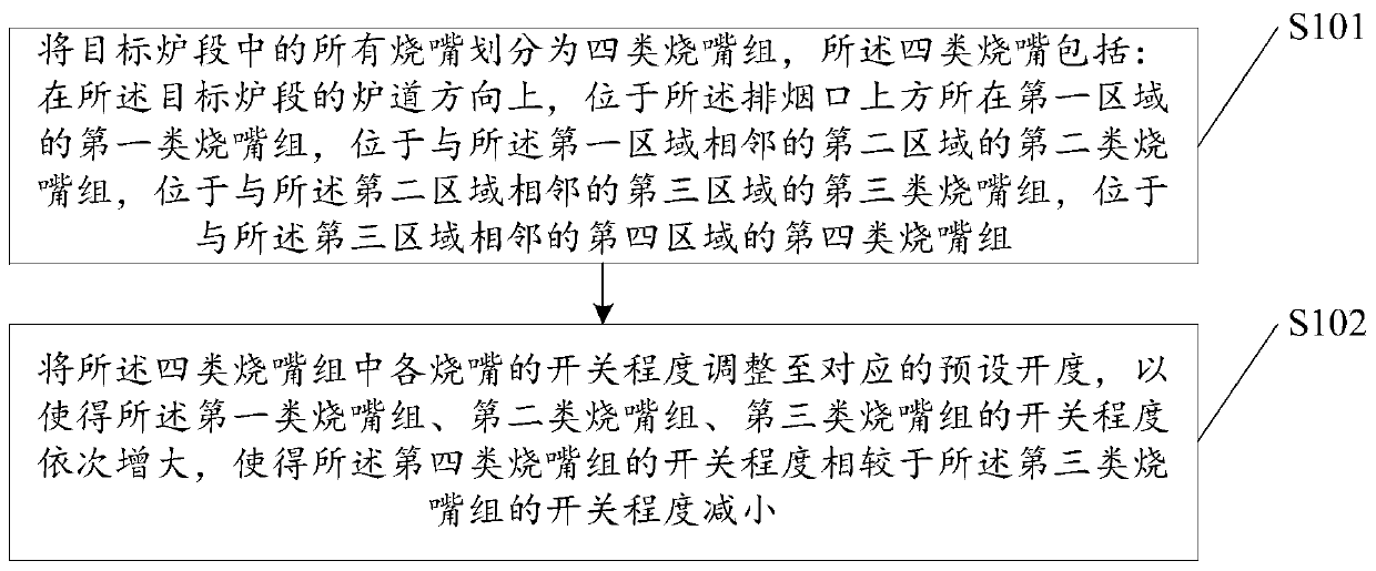
[0054] At present, the existing roller hearth type soaking furnace. The roller hearth type soaking furnace equipped behind the continuous casting machine of the existing CSP production line has a height and width of the furnace space of about 1.4m and 2m respectively. Specifically, the soaking furnace is divided into a heating section, a soaking section, a swing Each furnace section is equipped with a large number of burners along the length of the furnace for heating, and is divided into multiple temperature control areas of different numbers to ensure a reasonable furnace temperature distribution in the direction of the furnace length. For the emission of combustion flue gas in the furnace, a smoke exhaust port is provided at the bottom of the furnace in the middle area of ​​each furnace section, and the smoke exhaust port of the swing section is set at the end of the furnace section, which is convenient for the control of the furnace pressure and reasonable smoke discharge. ...

Embodiment 2

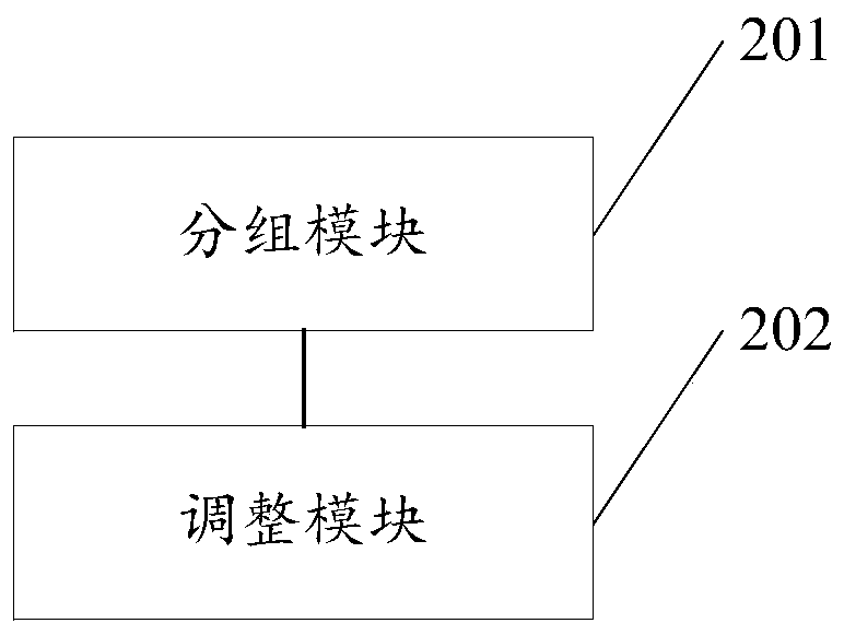
[0123] The embodiment of the present invention provides a burner control device for each section of the soaking furnace, such as figure 2 shown, including:

[0124] A grouping module 201, configured to divide all burners in the target furnace section into four types of burner groups, the four types of burners include: in the direction of the furnace path of the target furnace section, located above the smoke outlet The first type of burner group located in the first area, the second type of burner group located in the second area adjacent to the first area, and the third type of burner group located in the third area adjacent to the second area a burner group, a fourth-type burner group located in a fourth area adjacent to the third area;

[0125] The adjustment module 202 is used to adjust the switch degree of each burner in the four types of burner groups to the corresponding preset opening degree, so that the first type of burner group, the second type of burner group, th...


PUM


Abstract

The invention relates to the technical field of heating furnaces, in particular to a burners control method for each furnace section of a soaking pit, wherein a smoke outlet is formed in each furnacesection. The method comprises the following steps of dividing all burners in a target furnace section into four types of burner groups; and adjusting the switching degree of each burner in the four types of burner groups to a corresponding preset opening degree, so that the switch degree of the first type burner group, the second type burner group, and the third type burner group is increased in sequence, and the switch degree of the fourth type burner group is reduced compared with the switch degree of the third burner group, thus the false judgment of a secondary control system of the soaking pit caused by higher temperature of a zone far away from a smoke outlet is effectively avoided, a stable combustion state is still ensured when the discharge temperature of a slab is lower, a flameout phenomenon is avoided, a secondary combustion of the smoke outlet is also reduced, the energy consumption of the heating furnace is reduced, the heating instruction of the slab is improved, and theservice life of a heat exchanger is prolonged.

Description

technical field [0001] The invention relates to the technical field of heating furnaces, in particular to a method and device for controlling burners in each furnace section of a soaking furnace. Background technique [0002] At present, the existing soaking furnace is divided into a heating section, a soaking section, a swing section and a common heat preservation section. A certain number of burners are evenly arranged along the length of the furnace for heating in each section, and multiple burners of different numbers are arranged separately. The temperature control area is designed to ensure that the temperature of each section of the furnace can be reasonably controlled, and a smoke exhaust port is provided in each section to facilitate the emission of combustion flue gas in the furnace. The temperature of the existing continuous casting slabs is generally 850°C-1050°C, and the furnace temperature is 1120°C-1180°C. For the existing heat load distribution control metho...

Claims


Application Information

Patent Timeline
IPC IPC(8): C21D9/70C21D11/00
CPCC21D9/70C21D11/00
Inventor 罗巍刘义滔丁翠娇张超欧阳德刚陈猛朱善合刘刚峰
Owner 武汉钢铁有限公司
Learn More