

Laser coupling focusing mechanism
A laser and coupling mirror technology, applied in the field of optical instruments, can solve problems such as complex structure, no locking structure, defocusing, etc., and achieve the effect of simple mechanism principle, stable and reliable position, and high focus resolution
Inactive Publication Date: 2019-11-29
CHANGCHUN INST OF OPTICS FINE MECHANICS & PHYSICS CHINESE ACAD OF SCI
View PDF9 Cites 4 Cited by
- Summary
- Abstract
- Description
- Claims
- Application Information
AI Technical Summary
Problems solved by technology
[0003] Utility model patent CN201120109437.0 "a laser focusing head with a micrometer" uses a micrometer as a driving element to drive the focus lens to move to achieve laser focus adjustment. system, and there may be situations where the movement direction of the micrometer is not perpendicular to the optical axis, resulting in translation of the focus on the plane perpendicular to the optical axis;
[0004] Utility model patent CN200820235527.2 "a laser focusing device" uses a guide rail as the axial movement guide element of the focusing mirror, and drives the focusing slide to move along the guide rail through a screw. This structure is more suitable for large-aperture optical systems. For small-aperture The adoption of optical system, guide rail and screw structure leads to a larger overall structure, and the high-precision guide rail is expensive;
The structure is very complicated, the processing cost of the lens barrel guide rail and the fine-tuning cam is high, the accuracy is not easy to guarantee, and the nested structure of the three-layer lens barrel is prone to motion jamming when the temperature changes greatly. At the same time, the structure has no locking structure, and when there is vibration The moving lens barrel of the kit lens group will slide, resulting in defocus;
Method used
View moreImage
Smart ImageViewing Examples

Examples
Embodiment 1
[0037] Embodiment 1: The mechanism can also be directly applied to laser collimation applications to achieve fine adjustment of the divergence angle of the emitted laser beam. It can also be more widely used in all occasions that require optical focusing mechanism;
Embodiment 2
[0038] Embodiment 2: The mechanism is a technical solution for manual focusing. It can also be achieved by adding a stepping motor, transmission gear and other structures to realize the rotation of the fine-tuning sleeve electrically, that is, the principle of the focusing structure of the present invention can be expanded to achieve Electric focusing mechanism.
Login to View More PUM
 Abstract
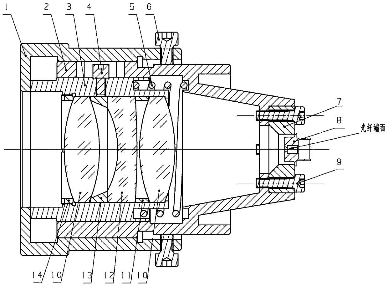
The invention discloses a laser coupling focusing mechanism and relates to the field of optical instruments. The device is technically characterized by comprising a fine adjustment sleeve, a main lenscone, a coupling lens group lens cone, a guide rod, a compression spring, multiple locking screws, an optical fiber connector seat, an optical fiber connector, a fixing screw, a pair of lenses A, a space ring A, a lens B, a space ring B and a pressing ring, wherein the main lens cone is arranged in the fine adjustment sleeve, the coupling lens group lens cone is arranged on the main lens cone, aleft end surface of the interior of the fine tuning lens cone is attached to a left end surface of the coupling lens group lens cone, a surface of the main lens cone is provided with a guide chute, the guide rod is sleeved in the guide chute on the main lens cone, the guide rod is fixed on an outer cylindrical surface of the coupling lens group lens cone through threads, a right end of the lens coupling lens group lens cone is provided with a spring mounting groove of the compression spring, a right end of a larger inner hole of the main lens cone is provided with a spring mounting groove, andthe compression spring is arranged between the two spring mounting grooves. The device is advantaged in that the structure is simple, machining cost is low, and adjustment is convenient.
Description
Technical field [0001] The invention relates to the technical field of optical instruments, in particular to a laser coupling focusing mechanism. Background technique [0002] In order to efficiently couple the laser into the fiber, the following conditions must be met: 1. The cone angle of the laser beam must be smaller than the maximum acceptance angle of the fiber, otherwise the total reflection will not be satisfied, and the loss will be large; 2. The laser beam must be perpendicular to the fiber end face; 3. The concentricity of the laser beam and the fiber end face should be high; 4. The focus of the coupling lens group should be on the fiber end face; 5. The fiber end face should be clean; 6. The laser spot is smaller than the fiber core diameter; 7. The maximum power that the fiber can withstand Greater than the laser power; 8. The turning radius of the fiber meets the requirements. An excellent laser coupling device should fully meet the requirements of the above condit...
Claims
Login to View More Application Information
Patent Timeline
 Patent Type & AuthorityApplications(China)
IPC IPC(8): G02B6/42G02B6/32
CPCG02B6/32G02B6/4204
Inventor伞晓刚高世杰丁少行倪迎雪盛磊耿天文陈云善
OwnerCHANGCHUN INST OF OPTICS FINE MECHANICS & PHYSICS CHINESE ACAD OF SCI