
Dielectric waveguide filter

A dielectric waveguide and filter technology, applied in the field of dielectric waveguide filters, can solve the problems of sacrificing the Q value of the filter, the deterioration of high-order harmonics, and increasing the difficulty of device design, achieving low processing difficulty, improving low-end suppression, reducing Effect of loss of Q value

Inactive Publication Date: 2019-11-29
SHENZHEN GRENTECH RF COMM LTD
View PDF5 Cites 1 Cited by
  • Summary
  • Abstract
  • Description
  • Claims
  • Application Information

AI Technical Summary

Problems solved by technology

This method is simple, but it will sacrifice a certain Q value of the filter, and at the same time, it will deteriorate the high-order harmonics to a certain extent
This method virtually increases the difficulty of device design

Method used


Image

  • Dielectric waveguide filter
  • Dielectric waveguide filter
  • Dielectric waveguide filter

Examples


Embodiment Construction

[0027] The present invention will be further described below in conjunction with the accompanying drawings and embodiments.

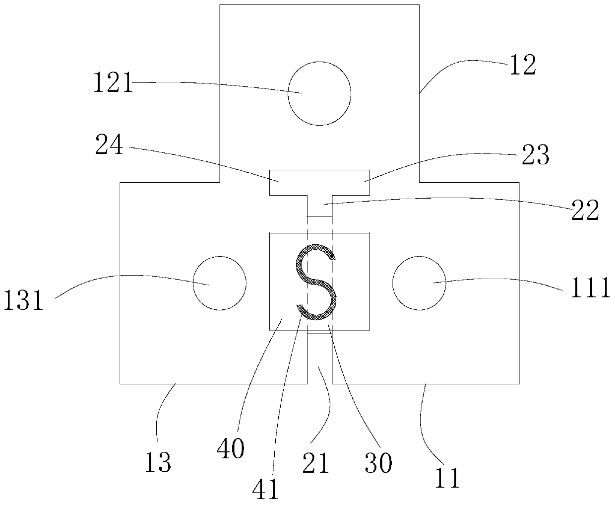
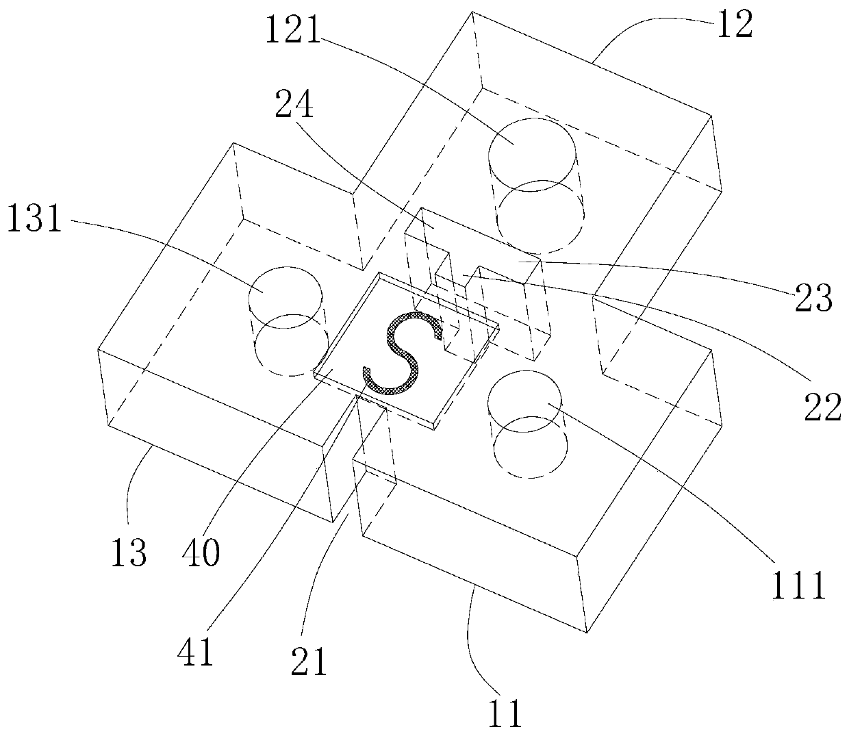
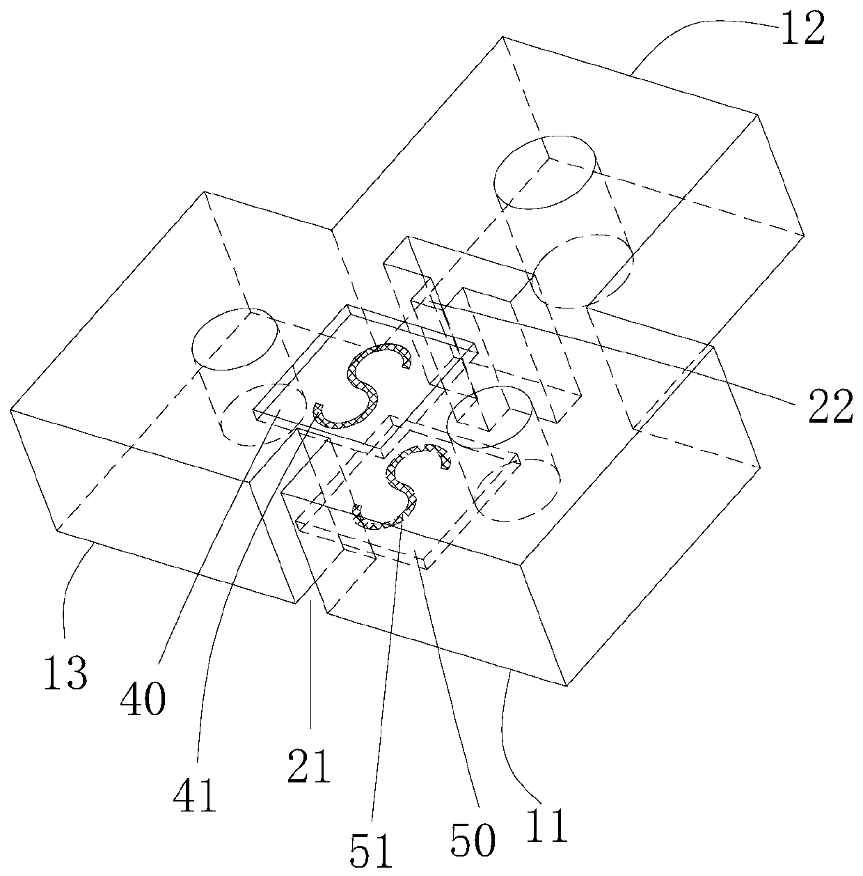
[0028] refer to figure 1 with figure 2 , a dielectric waveguide filter provided by the first embodiment of the present invention includes three dielectric resonators. The three dielectric resonators are a first dielectric resonator 11 , a second dielectric resonator 12 and a third dielectric resonator 13 . The first dielectric resonator 11 and the third dielectric resonator 13 are arranged side by side, and the second dielectric resonator 12 is located outside the connecting line between the first dielectric resonator 11 and the third dielectric resonator 13 . Each dielectric resonator includes a dielectric body such as a ceramic body and a conductive shielding layer coated on the outer surface of the dielectric. The conductive shielding layer is a metal layer such as a gold layer, a silver layer or a copper layer. The upper surface of each dielect...


PUM


Abstract

The invention relates to a dielectric waveguide filter which comprises two adjacent dielectric resonators. A coupling window is formed between the two dielectric resonators. A first sinking area is arranged on the upper surface of the coupling window. The two ends of the first sinking area respectively extend to the two dielectric resonators. The inner surface of the first sinking area is providedwith a conductive shielding layer. A first coupling polarity inversion structure is formed on the conductive shielding layer on the bottom surface of the first sinking area. The first coupling polarity inversion structure forms a non-conductive shielding area. The capacitive coupling between the two adjacent dielectric resonators can be realized, the loss of Q value can be reduced, the ratio of the transverse size of the first coupling polarity inversion structure to the width of the coupling window can be changed and inductive coupling or electromagnetic mixed coupling between the two dielectric resonators can also be realized.

Description

【Technical field】 [0001] The invention relates to the field of microwave communication, in particular to a dielectric waveguide filter. 【Background technique】 [0002] A filter is a frequency-selective device that is often used in the front end of an RF system. With the advent of the 5G era, systems are getting smaller and lighter. Miniaturization, high performance, and low power consumption filters are the key to the miniaturization of 5G equipment. Compared with traditional waveguide filters, dielectric waveguide filters have great advantages, so they have broad application prospects in 5G communication equipment. [0003] In order to improve the frequency selection characteristics of the dielectric waveguide filter, cross-coupling is usually used to make the phase difference 180°, thus forming a pole outside the passband of the frequency response. In the dielectric waveguide filter, the way to realize the capacitive coupling is usually to realize the blind hole with a ...

Claims


Application Information

Patent Timeline
IPC IPC(8): H01P1/20H01P7/10
CPCH01P1/2002H01P7/10
Inventor 章博段宗金
Owner SHENZHEN GRENTECH RF COMM LTD
Learn More