Machining system for milling cutter and machining method of machining system

A processing system and milling cutter technology, applied in milling cutters, metal processing equipment, milling machine equipment, etc., can solve the problems of low degree of automation and achieve the effect of improving the degree of automation

Inactive Publication Date: 2019-12-03
深圳市富吉真空技术有限公司
View PDF16 Cites 3 Cited by
  • Summary
  • Abstract
  • Description
  • Claims
  • Application Information

AI Technical Summary

Problems solved by technology

[0004] However, the existing milling cutter gear grinding machine needs to manually clamp and send the blank t

Method used


Image

  • Machining system for milling cutter and machining method of machining system
  • Machining system for milling cutter and machining method of machining system
  • Machining system for milling cutter and machining method of machining system

Examples


Embodiment

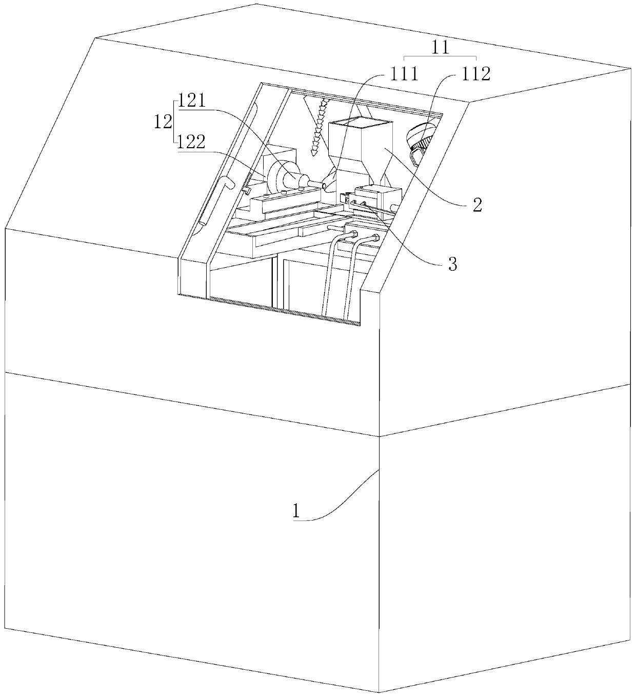
[0049] A kind of processing system and processing method thereof for milling cutter, refer to figure 1 , which includes a frame 1 , a grinding mechanism 11 and a clamping mechanism 12 . The clamping mechanism 12 is slidably connected inside the frame 1 along the direction approaching or away from the grinding mechanism 11. The clamping mechanism 12 can move along the length direction or the width direction inside the frame 1. The bottom of the clamping mechanism 12 is provided with a driving clamp The oil cylinder that mechanism 12 moves. The clamping mechanism 12 includes a clamping clamp 121 and a rotating motor 122 for driving the clamping clamp 121 to rotate. The blank is inserted into the clamping clamp 121 and clamped by the finger clamp cylinder in the clamping clamp 121 . The grinding mechanism 11 is fixedly connected inside the frame 1 , and the grinding mechanism 11 includes a grinding wheel 111 and a driving motor 112 for driving the grinding wheel 111 .

[0050] ...


PUM


Abstract

The invention discloses a machining system for a milling cutter and a machining method of the machining system, relates to the technical field of milling cutter manufacturing, and aims to solve the problems that in the using process of an existing milling cutter broken tooth grinding machine, a to-be-machined blank needs to be manually clamped to a clamping piece and the automation degree is quitelow; according to the technical scheme, the machining system is characterized by comprising a rack, a polishing mechanism and a clamping mechanism, the clamping mechanism is slidably connected to theinterior of the rack in the direction close to or away from the polishing mechanism, and the polishing mechanism is fixedly connected to the interior of the rack; a feeding mechanism used for automatically feeding blanks is arranged on the side, located on the grinding mechanism, of the rack, and a clamping discharging mechanism is arranged on the side, away from the grinding mechanism, of the feeding mechanism. The feeding mechanism comprises a storage bin, a feeding port and a feeding push rod, the storage bin is fixed to the side, located on the grinding mechanism, of the rack, the feedingport is formed in the bottom end of the storage bin, and the feeding push rod is connected to the bottom end of the feeding port in a sliding mode. The effects of automatically completing feeding ofthe steel blanks and improving the automation degree are achieved.

Description

technical field [0001] The invention relates to the technical field of milling cutter manufacturing, more specifically, it relates to a milling cutter processing system and a processing method thereof. Background technique [0002] A milling cutter is a rotating tool with one or more teeth for milling. When working, each knife tooth cuts off the allowance of the workpiece intermittently in turn. Milling cutters are mainly used for machining planes, steps, grooves, forming surfaces and cutting off workpieces on milling machines. [0003] The existing Chinese patent with publication number CN103846748A discloses a CNC milling cutter end tooth grinder, which includes a machine base, a cross carriage mechanism, a spindle system and a grinding wheel feeding device. The bracket is equipped with a column screw, a column servo motor and a lifting frame. The lifting frame slides and lifts on the bracket driven by the positive and negative rotation of the column screw. The lifting f...

Claims


Application Information

Patent Timeline
IPC IPC(8): B24B3/02B24B3/00B24B41/00B24B55/04B24B57/02B24B41/06
CPCB24B3/00B24B3/02B24B41/005B24B41/06B24B55/04B24B57/02
Inventor 李其金王立峰宋小利
Owner 深圳市富吉真空技术有限公司
Why Eureka
Try Eureka