
Dustproof structure for blast furnace top charging bucket

A dust-proof structure, blast furnace furnace technology, applied in the direction of the dust collector, bell and funnel arrangement, etc., can solve the problems of high labor intensity, easy to cause dust, abnormal feeding, etc., to achieve the effect of reducing dust cleaning operations

Inactive Publication Date: 2019-12-03
BAOSTEEL ZHANJIANG IRON & STEEL CO LTD
View PDF6 Cites 1 Cited by
  • Summary
  • Abstract
  • Description
  • Claims
  • Application Information

AI Technical Summary

Problems solved by technology

[0004] 1. Common corrugated pipes and material accumulation trays are used between the upper and lower material tanks. Due to the gap between the soft connection and the material tank, a large amount of dust is accumulated on the material accumulation plate during the feeding process, and it will be full in about two months. Affect the weight of the weighing tank, resulting in abnormal feeding, thus affecting the blast furnace condition and normal production of the blast furnace;
[0005] 2. Every time the blast furnace is repaired, it is necessary to arrange personnel to clean up the dust accumulation. At least 3 people are needed to complete the work. The labor intensity is high. Sometimes it is necessary to arrange personnel to clean up temporarily, and there are operational risks;
[0006] 3. During each cleaning process, it is easy to cause dust, damage the site environmental sanitation, and increase the workload of manual cleaning
[0007] At present, domestic and international blast furnaces all adopt this connection method, and the existing problems have not been solved, and only manual cleaning can be carried out

Method used


Image

  • Dustproof structure for blast furnace top charging bucket

Examples


Embodiment Construction

[0021] Below in conjunction with accompanying drawing and embodiment, the specific embodiment of the present invention is described in further detail. The following examples are used to illustrate the present invention, but are not intended to limit the scope of the present invention.

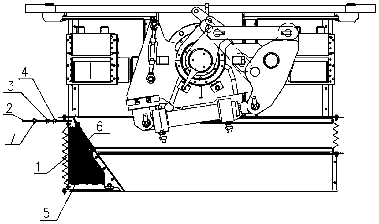
[0022] combine figure 1 As shown, the present invention provides a dust-proof structure for blast furnace roof tanks including a material accumulation platform, which is characterized in that, the outer side of the material accumulation platform adopts a bellows 1, and the bellows 1 is connected with a pipeline 2 outside the pipeline. 2 is connected with compressed air, and the pressure in the accumulating table is increased by introducing compressed air to avoid dust accumulation; the pipeline 2 is provided with a solenoid valve 3 and a pressure interlock switch 4, and the solenoid valve 3 and pressure interlock switch 4 are connected to the The background system is connected. When the upper ...


PUM


Abstract

The invention relates to a dustproof structure for a blast furnace top charging bucket. The dustproof structure comprises a material accumulation table, wherein a corrugated pipe is arranged on the outer side of the material accumulation table; a pipeline is connected outside the corrugated pipe; compressed air is communicated with the pipeline; the pipeline is provided with a manual valve, an electromagnetic valve and a pressure interlocking switch; the electromagnetic valve and the pressure interlocking switch are connected with a background system; hard sponge is arranged on the inner wallof the corrugated pipe; the hard sponge is divided into at least three blocks along the inner wall and the blocks of the sponge are connected with each other through bolts; a plurality of pieces of soft sponge are arranged on the other side of the hard sponge. The pressure intensity is increased through additionally arranging the dustproof structure and compressed air; dust is prevented from beingaccumulated between the corrugated pipe connected between an upper material tank and a lower material tank and the material tank; the weighing of the lower material tank is prevented from being influenced, and stable and smooth production of the blast furnace is guaranteed. On-site ash removal operation is reduced, energy conservation and environmental protection are achieved, and on-site flyingdust is prevented from polluting the environment.

Description

technical field [0001] The invention belongs to the technical field of blast furnace top maintenance, and in particular relates to a dustproof structure for blast furnace top charging tanks. Background technique [0002] Raw materials for blast furnace smelting are screened and weighed by the raw material system, and then sent to the blast furnace through the furnace top equipment feeding tank, upper gate valve, upper sealing valve, lower material tank, material flow valve, lower sealing valve, and distributor for the blast furnace In smelting production, the feeding tank is a weighing tank, and the material flow valve is opened to different openings according to different material weights and cloth distribution circles, so the weighing of the feeding tank directly affects the distribution of materials in the blast furnace. With the continuous improvement of blast furnace smelting technology, modern blast furnaces are developing in the direction of large scale, high efficien...

Claims


Application Information

Patent Timeline
IPC IPC(8): C21B7/22C21B7/18
CPCC21B7/18C21B7/22
Inventor 苏威梁利生任玉军
Owner BAOSTEEL ZHANJIANG IRON & STEEL CO LTD
Learn More