Tunneling drilling machine

A technology for excavating drilling rigs and drilling rigs, which is applied in drilling equipment, cutting machinery, earth-moving drilling and mining, etc., can solve the problems of time-consuming and laborious, small drilling range, etc., and achieve the effect of increasing drilling range and improving efficiency.

Pending Publication Date: 2019-12-03
SANY HEAVY EQUIP
View PDF0 Cites 1 Cited by
  • Summary
  • Abstract
  • Description
  • Claims
  • Application Information

AI Technical Summary

Problems solved by technology

[0002] At present, most coal-rock and semi-coal-rock roadways have gas or water permeation accidents. Before the roadheader cuts, it is necessary to drill holes for gas and water on the roadway section. The general working condition is manual drilling by workers, which is time-consuming and laborious. To solve the above problems A drilling rig integrating the drilling rig and the roadheader is proposed. The oil passage of the roadheading machine is used to realize the automatic drilling of the drilling rig and reduce the labor force of the workers. However, this kind of drilling machine has the problem of small drilling range.

Method used


Image

  • Tunneling drilling machine
  • Tunneling drilling machine
  • Tunneling drilling machine

Examples


Embodiment 1

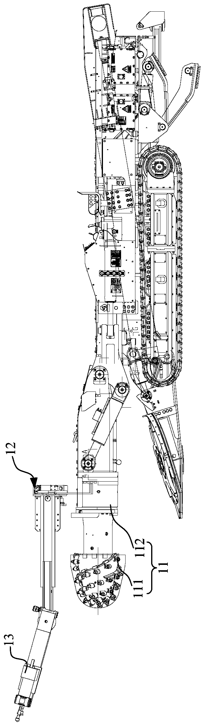
[0048] Such as Figure 5 As shown, in addition to the features described in the above embodiments, it is further defined that: the first track 121 is provided with a stopper 122, and the stopper 122 divides the first track 121 into a first sliding area 1201 and a second sliding area In zone 1202 , two drilling machines 131 are set in one-to-one correspondence with the first sliding zone 1201 and the second sliding zone 1202 . The partition of the first track 121 is realized by the stopper 122, and the two drilling machines 131 move in their respective sliding areas, so as to avoid the mutual interference of the two drilling machines 131 during the movement, collision and other accidents, and further improve the drilling machine 131. operational reliability.

[0049] Further, the stop portion 122 is located in the middle area of ​​the first track 121 . In this way, the stopper 122 roughly divides the first rail 121 into two sliding areas, the range of motion of the two drilli...

Embodiment 2

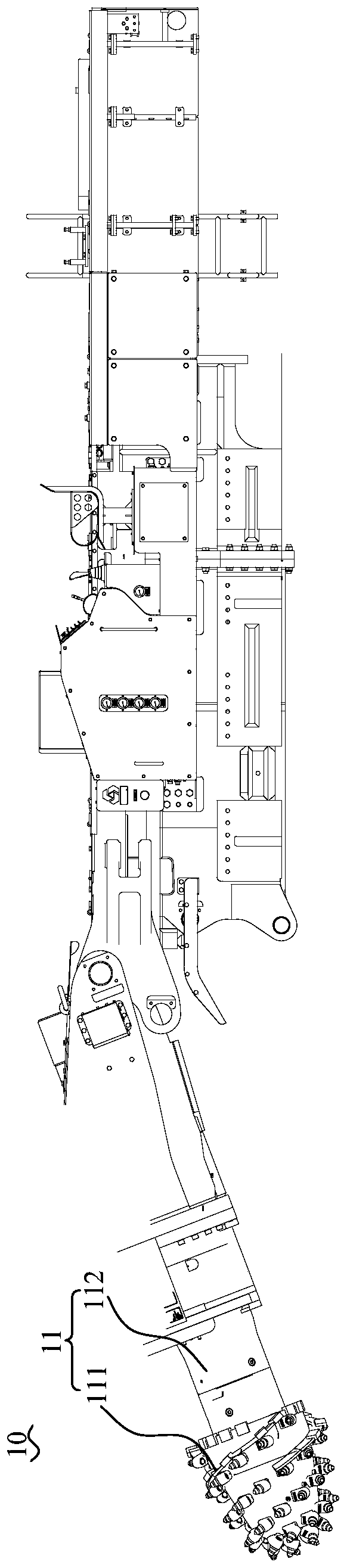
[0052] Such as Figure 5 and Figure 6 As shown, in addition to the features described in the above embodiments, it is further defined that: the first track 121 is arc-shaped. For example, the first track 121 is in the shape of an arc with the middle protruding upwards and the left and right ends extending downwards. In this way, the arc-shaped track further increases the range of motion of the drilling machine 131 in vertical height, thereby increasing the drilling capacity of the drilling machine 131. In addition, the arc-shaped track design makes the trajectory of the drilling machine 131 roughly arc-shaped, which is more suitable for construction environments such as roadways that require arching.

[0053] Certainly, in other embodiments, a track 121 may also be designed to be linear.

Embodiment 3

[0055] Such as Figure 5 , Figure 7 and Figure 8 As shown, in addition to the features described in the above embodiments, it is further defined that: the slide rail assembly 12 includes two mounting seats 123, and the two mounting seats 123 are respectively slidingly connected with the first rail 121, and the two drilling machines 131 are connected with the first rail 121. The two installation bases 123 are correspondingly connected, and the installation base 123 moves along the first rail 121 to make the drilling machine 131 connected thereto move. In this way, the sliding connection between the drilling machine 131 and the first slide rail is realized through the mounting seat 123, so that the connection between the drilling machine 131 and the first slide rail is more stable and reliable.

[0056] Further, as Figure 6 , Figure 11 and Figure 12 As shown, the mounting base 123 is provided with a plurality of pulleys 124 , the first track 121 is provided with a pull...


PUM


Abstract

The invention provides a tunneling drilling machine. A tunneling part, a sliding rail assembly and a drilling machine part are included. The sliding rail assembly is arranged on the tunneling part andcomprises a first track, and the included angle is formed between the first track and the tunneling part. The drilling machine part comprises two boring machines which are in sliding connection withthe first track, the boring machines slide along the first track, and accordingly the drilling machine part moves relative to the tunneling part. According to the tunneling drilling machine provided in the scheme, the drilling machine part slides along the first track so that the drilling machine part can move relative to the tunneling part, the first track is used for releasing the freedom degreefor the movement of the drilling machine part relative to the tunneling part, for example, the first track stretches across the left side and the right side of the tunneling part, the drilling machine part can move between the left side and the right side of the tunneling part, the boring machines are more flexible, the boring range of the boring machines is further enlarged, in the scheme, the two boring machines can conduct boring work, and the boring efficiency is improved.

Description

technical field [0001] The invention relates to the field of drilling machines, in particular to a drilling machine. Background technique [0002] At present, most coal-rock and semi-coal-rock roadways have gas or water permeation accidents. Before the roadheader cuts, it is necessary to drill holes for gas and water on the roadway section. The general working condition is manual drilling by workers, which is time-consuming and laborious. To solve the above problems A drilling rig integrating the drilling rig and the roadheader is proposed. The oil passage of the roadheading machine is used to realize the automatic drilling of the drilling rig and reduce the labor force of the workers. However, this kind of drilling machine has the problem of small drilling range. Contents of the invention [0003] In order to solve at least one of the above technical problems, an object of the present invention is to provide a drilling machine. [0004] In order to achieve the above obje...

Claims


Application Information

Patent Timeline
Patent Type & Authority Applications(China)
IPC IPC(8): E21C25/66E21C35/00E21B15/00
CPCE21B15/003E21C25/66E21C35/00
Inventor 李文泷闫海博李楠楠
Owner SANY HEAVY EQUIP
Why Eureka
Try Eureka