
Novel wheel type acting device

A working and wheeled technology, applied in stators, engine components, machines/engines, etc., can solve the problems of reducing volume and weight, low energy conversion efficiency, etc.

Pending Publication Date: 2019-12-03
于魁江
View PDF0 Cites 0 Cited by
  • Summary
  • Abstract
  • Description
  • Claims
  • Application Information

AI Technical Summary

Problems solved by technology

[0003] The technical problem to be solved by the present invention is to provide a new type of wheel-type work device that can achieve the same work effect as the multi-stage work impeller in view of the deficiencies in the prior art. Perform work on the impeller blades multiple times, that is, let the same high-energy gas perform work on the impeller blades multiple times on a single work impeller, achieve the work effect that can only be achieved by a multi-stage work impeller mechanism, and improve the energy conversion of high-energy gases on a single work impeller Efficiency, improving the low energy conversion efficiency of a single power impeller, reducing the number of individual power impellers with the same energy conversion efficiency, reducing the volume and weight, reducing its manufacturing cost, and making the wheeled power device available on land. widely used and popularized

Method used


Image

  • Novel wheel type acting device
  • Novel wheel type acting device
  • Novel wheel type acting device

Examples


Embodiment Construction

[0049] In order to more clearly illustrate the technical features of the new wheeled power device, the scheme will be further elaborated below through ten implementation modes combined with the accompanying drawings.

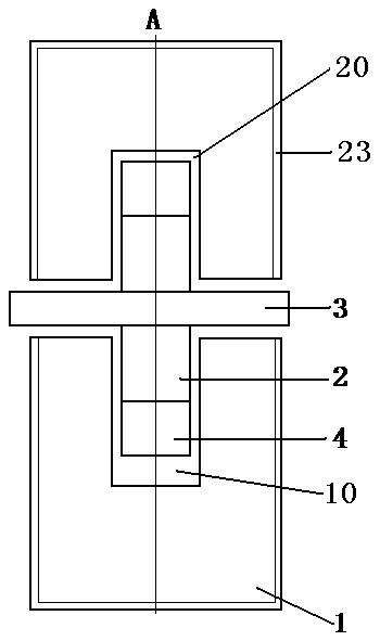
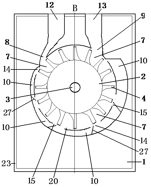
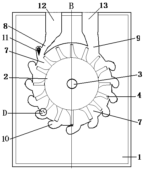
[0050]figure 1 , figure 2 Shown is the first embodiment of the new wheeled work device. It can be seen from the accompanying drawings that the new wheeled work device shown in this embodiment is mainly composed of a casing 1 and an impeller, and the casing 1 has a thermal insulation layer 23, the thermal insulation layer 23 has thermal insulation material, and the impeller is composed of a wheel body 2, an axle 3, and blades 4, and the blades 4 are installed on the outer circumference of the wheel body 2, and the center of the wheel body 2 is equipped with Axle 3, the impeller is installed in the impeller wheel chamber 20 in the housing 1, the size of the impeller wheel chamber 20 matches the impeller, the impeller and the inner wall of the wheel chamber 20 mai...


PUM


Abstract

The invention provides a technical scheme of a novel wheel type acting device. According to the scheme, the centrifugal fan comprises a shell and an impeller, the impeller is composed of an impeller body, an impeller shaft and blades. The blades are fixed on the wheel body; the wheel body is fixed to the wheel shaft and installed in an inner wheel cavity of the shell. A bearing is arranged in thewheel shaft upper shell; tongue pieces with the same width as the blades are arranged on the anticlockwise sides of the top edges of the blades; the other edge of the tongue piece can slide up and down along the blade surface of another adjacent blade by taking the connecting shaft as the axis; an auxiliary cavity is formed in the periphery of the wheel cavity, corresponding to the impeller blades, of the semicircle, farthest away from the exhaust port, of the air inlet of the wheel cavity in the shell and communicated with the wheel cavity; a control valve is arranged on the air inlet; the air inlet is communicated with the air inlet channel; the exhaust port is communicated with the exhaust channel.

Description

technical field [0001] The invention relates to a work machine, in particular to a wheeled work device. Background technique [0002] Among the existing technologies, the technology closest to this application is a patent for a new type of pneumatic impeller with a patent number of 2013100075126 filed on January 9, 2013. In this patented technology, the number of times the high-energy gas acts on the impeller blades is one week. Once, that is to say, the high-energy gas only acts on each blade of the impeller once per rotation of the impeller, which is a typical single-stage power impeller. The energy conversion efficiency of a single-stage power turbine is relatively low, especially at low speeds. , higher fuel consumption, and smaller output torque. In order to improve energy conversion efficiency, reduce fuel consumption, and increase output torque, the typical representative of wheeled power devices in the prior art is a turbine engine, which is installed in series with ...

Claims


Application Information

Patent Timeline
IPC IPC(8): F01D9/02
CPCF01D9/02
Inventor 于魁江
Owner 于魁江
Learn More