A stepped oblique flow spiral baffle heat exchanger

A technology of helical baffles and baffles, applied in indirect heat exchangers, heat exchanger types, heat exchanger shells, etc. Difficulty in processing and assembling, to achieve the effect of reducing the burst rate, enhancing the stability, and enhancing the heat transfer coefficient of the shell side

Active Publication Date: 2021-01-12
ZHEJIANG UNIVERSITY OF SCIENCE AND TECHNOLOGY +1
View PDF7 Cites 0 Cited by
  • Summary
  • Abstract
  • Description
  • Claims
  • Application Information

AI Technical Summary

Problems solved by technology

[0005] The present invention mainly solves the technical problems of the existing spiral baffles in the prior art, which are either difficult to process and assemble or high in production cost, or have leakage in the triangular area between two connected baffles, and provide an easy-to-process, assemble, low-cost Step oblique flow helical baffle heat exchanger with low pressure and can avoid leakage in the triangular area between two connected baffles

Method used


Image

  • A stepped oblique flow spiral baffle heat exchanger
  • A stepped oblique flow spiral baffle heat exchanger
  • A stepped oblique flow spiral baffle heat exchanger

Examples


Embodiment 1

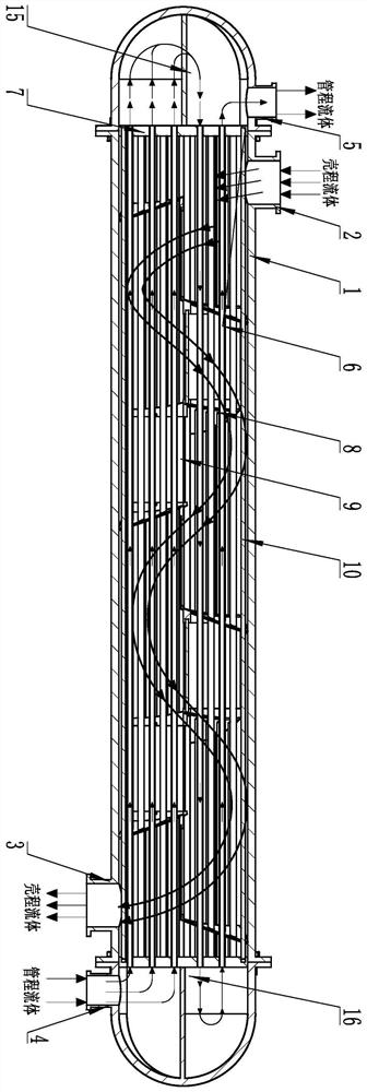
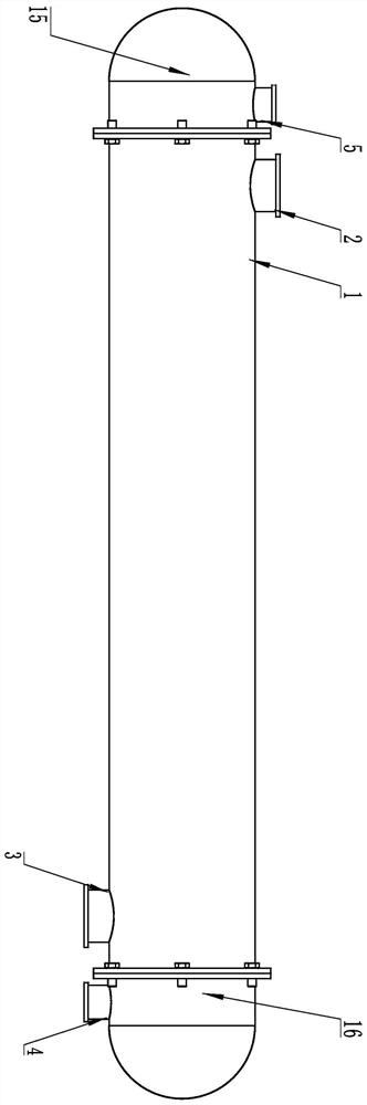
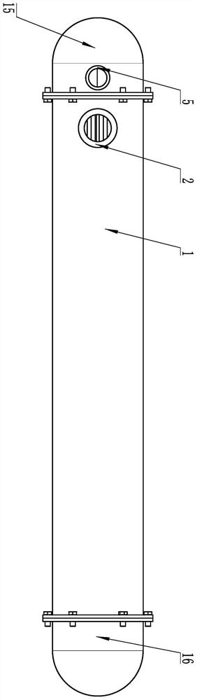
[0054] according to Figure 1 to Figure 7 and Figure 10 to Figure 15 A stepped oblique flow spiral baffle heat exchanger is shown, which includes a shell 1 and a head. The shell 1 is provided with a shell-side fluid inlet connection 2 and a shell-side fluid outlet connection 3. The A pipe-side fluid inlet connection pipe 4 and a pipe-side fluid outlet connection pipe 5 are arranged on the head of the pipe side, and several heat exchange tubes 6 are longitudinally arranged in the housing 1, and the two ends of the heat exchange pipes 6 pass through the The tube sheet 7 at the port of the housing 1 communicates with the head, and it is characterized in that, the housing 1 is provided with several sets of helical periodic baffle groups, and each group of the helical periodic baffles The plate group includes several oblique flow curved baffles 8 arranged in the spiral circumferential direction and with different phases. The oblique flow curved baffles 8 form a certain inclinatio...

Embodiment 2

[0059] Such as Figure 10 to Figure 16 and Figure 7 As shown, the difference between this embodiment and Embodiment 1 is that: each group of the spiral periodic baffles includes three oblique flow curved surface baffles 8, and the oblique flow curved surface baffles The axial projection of the plate 8 is fan-shaped and the fan-shaped angle is 120°. The oblique flow curved baffle 8 in the housing 1 is composed of three sets of oblique flow curved baffles 8. .

[0060] Compared with Embodiment 1, this embodiment makes further limitations on the oblique flow curved baffle 8 .

Embodiment 3

[0062] Such as Figure 10 and Figure 21 As shown, the difference between this embodiment and Embodiment 1 is that: the end of the oblique flow curved baffle 8 and the baffle 9 protrudes toward the side of the baffle 9 with a block 11. The block 11 is provided with a slot 12 that is compatible with the baffle 9, and the baffle 9 and the block 11 are both horizontally coaxially provided with equal-diameter pins A hole 13, the pin hole 13 is provided with a cylindrical pin 14 adapted to the pin hole 13.

[0063] Compared with Embodiment 1, this embodiment further limits the curved baffles 8 for oblique flow. When assembling, firstly insert the curved baffles 8 for oblique flow into the slots 12 one by one, and then insert the cylindrical pins 14. Several sets of helical periodic baffles are formed in the pins, and then the heat exchange tubes 6 and the tie rods 10 are inserted in sequence, and then the whole is inserted into the shell 1, and the tube sheets 7 are sealed at bot...


PUM


Abstract

The invention relates to a stepped oblique flow spiral baffle plate heat exchanger. A plurality of groups of spiral periodic baffle plate groups are arranged in the shell; each spiral periodic baffleplate group comprises a plurality of oblique flow curved surface baffle plates which are spirally arranged in the circumferential direction and have different phases; a certain inclination angle is formed between the inclined flow curved surface baffle plate and the cross section of the shell; every two adjacent oblique flow curved surface baffle plates in the shell are connected with a baffle plate through two adjacent straight edges located on the corresponding oblique flow curved surface baffle plate to form a step shape. The oblique flow curved surface baffle plates with the same phase inthe shell form an oblique flow curved surface baffle plate group, wherein the oblique flow curved surface baffle plate group in the same group is supported by a plurality of pull rods, and the pull rods are fixedly connected with the tube plate. The stepped oblique flow spiral baffle plate heat exchanger is easy to machine and assemble, low in cost and capable of avoiding flow leakage of a triangular area between two connected baffle plates.

Description

technical field [0001] The invention relates to a shell-and-tube heat exchanger, in particular to a stepped oblique flow spiral baffle heat exchanger with excellent structure. Background technique [0002] The shell and tube heat exchanger is composed of shell, heat transfer tube bundle, tube sheet, baffle (baffle) and tube box and other components. The shell is mostly cylindrical, with a tube bundle inside, and the two ends of the tube bundle are fixed on the tube sheet. There are two kinds of hot and cold fluids for heat exchange, one flows inside the tube, called tube-side fluid; the other flows outside the tube, called shell-side fluid. In order to improve the heat transfer coefficient of the fluid outside the tube, several baffles are usually installed in the shell. The baffle can change the flow direction of the shell-side fluid, forcing the fluid to flush the tube bundle horizontally multiple times according to the diversion path, and enhance the turbulence intensit...

Claims


Application Information

Patent Timeline
Patent Type & Authority Patents(China)
IPC IPC(8): F28D7/16F28F9/24F28F9/02F28F11/00
CPCF28D7/1607F28F9/02F28F9/24F28F11/00
Inventor 董聪黄永丽叶超郭文文夏玉珍叶阳辉卜钟鸣朱行丁铭侍园园
Owner ZHEJIANG UNIVERSITY OF SCIENCE AND TECHNOLOGY
Why Eureka
Try Eureka