
Detection system of infrared thermal imaging equipment

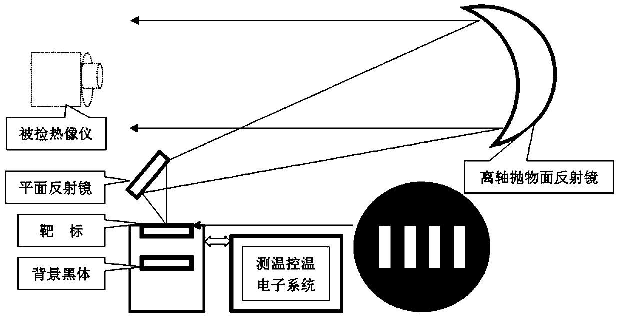
A technology of infrared thermal imaging and equipment, applied in the direction of control/regulation system, measuring device, optical radiation measurement, etc., can solve the problems of non-collimated optical system, difficult to use in-situ detection, inconvenient use, etc., and achieve reduced volume and weight , Simplify the structure and reduce the cost

Pending Publication Date: 2019-12-03
宋振铎
View PDF0 Cites 2 Cited by
  • Summary
  • Abstract
  • Description
  • Claims
  • Application Information

AI Technical Summary

Problems solved by technology

[0005] For this reason, the purpose of the present invention is to propose a detection system for infrared thermal imaging equipment, which has no collimation optical system, directly detects the comprehensive parameters of infrared thermal imaging equipment by observing the target with the detected infrared thermal imaging equipment, and effectively improves The applicability and practicability of detection effectively solve the problems of inconvenient portability and field use, difficulty in in-situ detection, and high price, and it is simple and easy to implement

Method used


Image

  • Detection system of infrared thermal imaging equipment
  • Detection system of infrared thermal imaging equipment
  • Detection system of infrared thermal imaging equipment

Examples


Embodiment Construction

[0033] Embodiments of the present invention are described in detail below, examples of which are shown in the drawings, wherein the same or similar reference numerals designate the same or similar elements or elements having the same or similar functions throughout. The embodiments described below by referring to the figures are exemplary and are intended to explain the present invention and should not be construed as limiting the present invention.

[0034] Before introducing the detection system and method of the infrared thermal imaging device proposed by the present invention, a brief introduction to related technologies will be given first.

[0035] Black body radiation obeys Planck's law: it describes the law of the ideal black body radiation emission Me(λ, T) with the wavelength λ changing with the temperature T, and the expression is shown in formula 1:

[0036]

[0037] In the formula: C 1 and C 2 are the first and second radiation constants, respectively.

[00...


PUM


Abstract

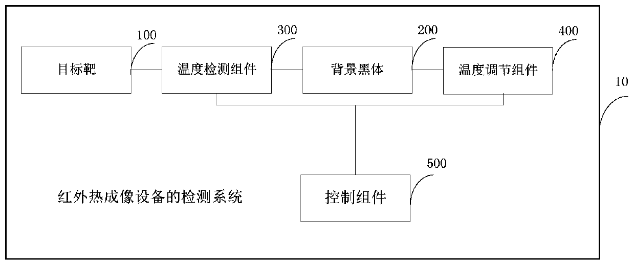
The invention provides a detection system of infrared thermal imaging equipment. The system comprises a target, a background blackbody, a temperature detection component, a temperature regulation component and a control component, wherein current temperature of the target and current temperature of the background blackbody are collected; the temperature regulation component is used for raising orlowering the current temperature of the background blackbody; and the control component controls the temperature regulation component to regulate the current temperature of the background blackbody, so that when a current temperature difference between the target and the background blackbody is consistent with a set target temperature difference, the to-be-detected infrared thermal imaging equipment generates a thermal image, and a detection result is obtained according to the thermal image. Through the system in the embodiment, the infrared thermal imaging equipment can directly generate thethermal image of the target without a collimation optical system, the thermal image is used for a detector to observe and detect comprehensive parameters of the target, the problems that other infrared thermal imaging equipment detection systems are inconvenient to carry and use in an external field, difficult to use in in-situ detection, high in price, low in precision and the like are effectively solved, and the system is simple in structure and easy to realize.

Description

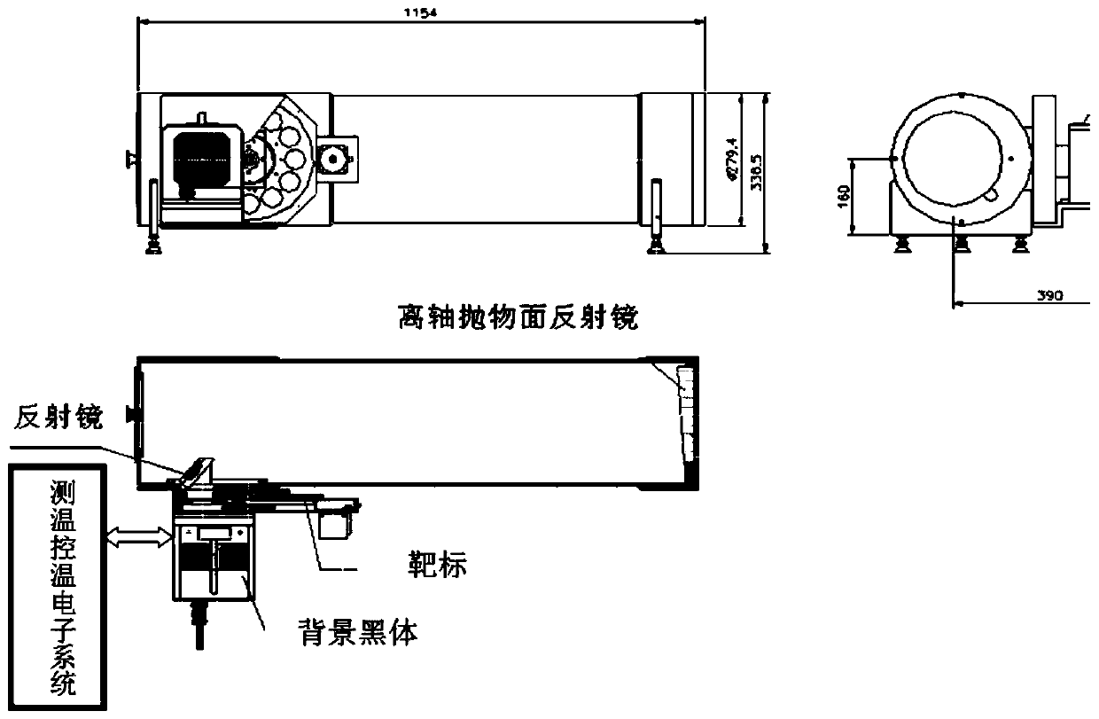
technical field [0001] The invention relates to the technical field of infrared thermal imaging equipment, in particular to a detection system of infrared thermal imaging equipment. Background technique [0002] The comprehensive parameters of infrared thermal imaging equipment include NETD (noise-equivalent temperature difference, hereinafter referred to as noise-equivalent temperature difference), MRTD (minimum resolvable temperature difference, minimum resolvable temperature difference) and MDTD (minimum detectable temperature difference, minimum detectable temperature difference). At present, the same detection equipment with collimating optical system is used to complete the detection of these three parameters at home and abroad, but the shape of the target is different. The basic components of the device include a target, a background blackbody, an electronic system for temperature measurement and temperature control of the target and the background blackbody, and a co...

Claims


Application Information

Patent Timeline
Patent Type & Authority Applications(China)
IPC IPC(8): G01J5/52G05D23/20
CPCG05D23/20G01J2005/0077G01J5/80G01J5/53
Inventor 宋振铎石鑫宋鸿鸣李召
Owner 宋振铎
Learn More