
Bistatic MIMO radar array diagnosis method based on subspace clustering

A technology of radar array and diagnosis method, which is applied in the direction of radio wave measurement system, instrument, etc., can solve the problems of reducing radar transmission power, failure of array elements in transceiver array, missing data at receiving end, etc., and achieves improvement of real-time performance and intelligence, Good stability and practicability, the effect of wide applicability

Active Publication Date: 2019-12-03
NANJING UNIV OF INFORMATION SCI & TECH
View PDF7 Cites 4 Cited by
  • Summary
  • Abstract
  • Description
  • Claims
  • Application Information

AI Technical Summary

Problems solved by technology

[0003] In practical applications, the transceiver array of MIMO radar is often composed of multiple transceiver elements. Due to the limitation of the life of components and the influence of harsh environments such as vibration, high temperature, and corrosion, the transceiver array will fail after long-term operation.
The faulty array elements in the transmitting array cannot normally radiate electromagnetic wave signals to space, which reduces the radar transmission power and shortens the radar operating distance; the faulty array elements in the receiving array cannot receive useful signals, resulting in data loss at the receiving end and reducing target parameter estimation performance
Existing detection methods for radar arrays require the use of additional test elements or test circuits, and have a large amount of calculation. They cannot complete the diagnosis of faulty elements in the MIMO radar transceiver array in a short time, so they are not suitable for complex tasks such as battlefields and spaceborne radars. occasion

Method used


Image

  • Bistatic MIMO radar array diagnosis method based on subspace clustering
  • Bistatic MIMO radar array diagnosis method based on subspace clustering
  • Bistatic MIMO radar array diagnosis method based on subspace clustering

Examples


Embodiment Construction

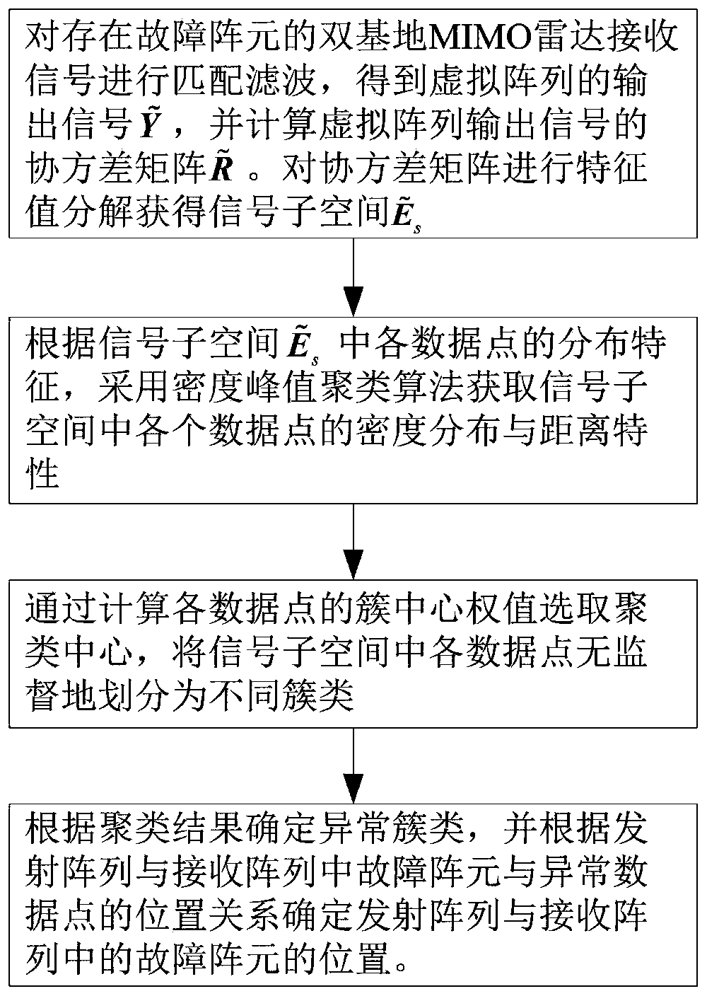
[0032] The implementation steps of the present invention will be described in detail below in conjunction with the accompanying drawings. Such as figure 1 Shown, the present invention comprises the following steps:

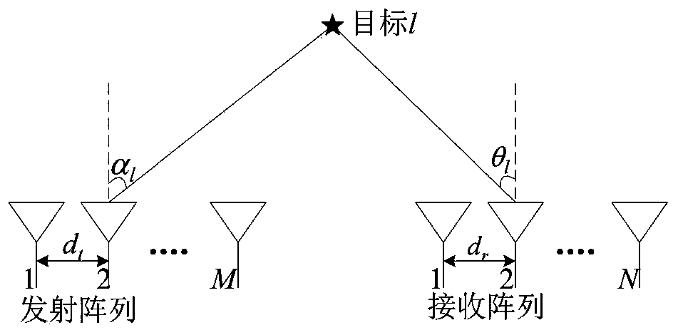
[0033] Step 1: If figure 2 As shown, it is assumed that the transmitting and receiving arrays of the bistatic MIMO radar are composed of M transmitting elements and N receiving elements respectively, and both the transmitting array and the receiving array are uniform linear arrays, and the distance between the elements is d t and d r , there are L non-coherent targets in the same distance unit in the space far field, and the launch angle (Direction of Departure, DOD) and reception angle (Direction of Arrival, DOA) of the l (l=1, 2,..., L) target respectively α l and θ l . M transmitting array elements transmit M narrow-band phase-encoded signals that are mutually orthogonal at the same frequency, and they satisfy in for the mth 1 The transmitting signa...


PUM


Abstract

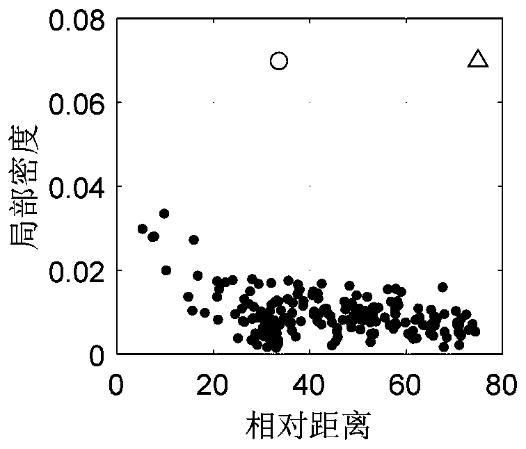
The invention discloses a bistatic MIMO radar array diagnosis method based on subspace clustering. The method comprises a step of performing eigenvalue decomposition on a virtual array covariance matrix to obtain a signal subspace and obtaining density distribution and distance characteristics of each data point in the signal subspace by using a density peak clustering algorithm according to distribution characteristics of each data point in the signal subspace, a step of selecting a clustering center by calculating a cluster center weight of each data point, dividing each data point in the signal subspace into different clusters in an unsupervised manner and determining an abnormal cluster, and a step of finally determining the positions of fault array elements in a transmitting array anda receiving array according to a data point in the abnormal cluster. By the adoption of the method, the fault array elements in the transmitting array and the receiving array can be diagnosed at thesame time, and extra test array elements or reference data are not needed.

Description

technical field [0001] The invention belongs to the field of radar fault array element diagnosis, and in particular relates to a bistatic MIMO radar array diagnosis method based on subspace clustering. Background technique [0002] Multiple Input Multiple Output (MIMO) radar, as a new system radar, has greatly improved the performance of target detection and parameter estimation due to its waveform diversity, space diversity and many other technologies, and has won the research and attention of many scholars. focus on. According to different configurations of transceiver arrays, MIMO radars can be divided into statistical MIMO radars and single (dual) base MIMO radars. Among them, the interval between the receiving and receiving elements of the single (double) base MIMO radar is relatively small, each channel of the transmitting array transmits mutually orthogonal coded waveforms, and a large number of virtual array elements are formed at the receiving end through matched f...

Claims


Application Information

Patent Timeline
IPC IPC(8): G01S7/40
CPCG01S7/4008G01S7/4021
Inventor 陈金立张廷潇李家强
Owner NANJING UNIV OF INFORMATION SCI & TECH
Learn More