Spark plug ignition device and method in combustion chamber of small rotary engine

A technology of rotary engine and ignition device, applied in engine ignition, spark ignition controller, combustion engine, etc., can solve the problems of difficult ignition and long flame propagation distance, so as to reduce the flame propagation distance, improve overall performance, reduce Effects of Airflow Loss

Active Publication Date: 2021-01-01
BEIJING INSTITUTE OF TECHNOLOGYGY
View PDF7 Cites 0 Cited by
  • Summary
  • Abstract
  • Description
  • Claims
  • Application Information

AI Technical Summary

Problems solved by technology

[0007] Aiming at the problems caused by the ignition chamber and spark plug channel of the ignition device of the traditional small rotor engine, the flame propagation distance is long, the ignition is difficult, the energy loss is serious, and the blow-by gas is serious when the sealing sheet is swept, etc., the invention discloses a small rotor engine. The technical problem to be solved by the spark plug ignition device and method in the combustion chamber of the engine is to provide a spark plug ignition device and method that does not require an ignition chamber and a spark plug channel, that is, to use a small rotor engine to directly ignite in the combustion chamber cylinder, so that the position of the spark plug is ignited. The interior of the ignition chamber is improved to the interior of the combustion chamber, and at the same time, the ignition chamber and the spark plug channel are isolated from the combustion chamber, so that the structure of the ignition chamber and the spark plug channel is omitted in the ignition device, and the long flame propagation distance caused by this structure is avoided. , Difficulty in ignition, serious energy loss, severe gas blow-by when the sealing plate is swept, that is, by removing the ignition chamber and spark plug channel, the following advantages are brought: (1) Reduce energy loss and reduce the probability of gas blow-by in two adjacent cylinders ; (2) The compression ratio can also be improved without changing the rest of the structure, and the smaller the size of the engine, the greater the increase in the compression ratio

Method used


Image

  • Spark plug ignition device and method in combustion chamber of small rotary engine
  • Spark plug ignition device and method in combustion chamber of small rotary engine
  • Spark plug ignition device and method in combustion chamber of small rotary engine

Examples


Embodiment 1

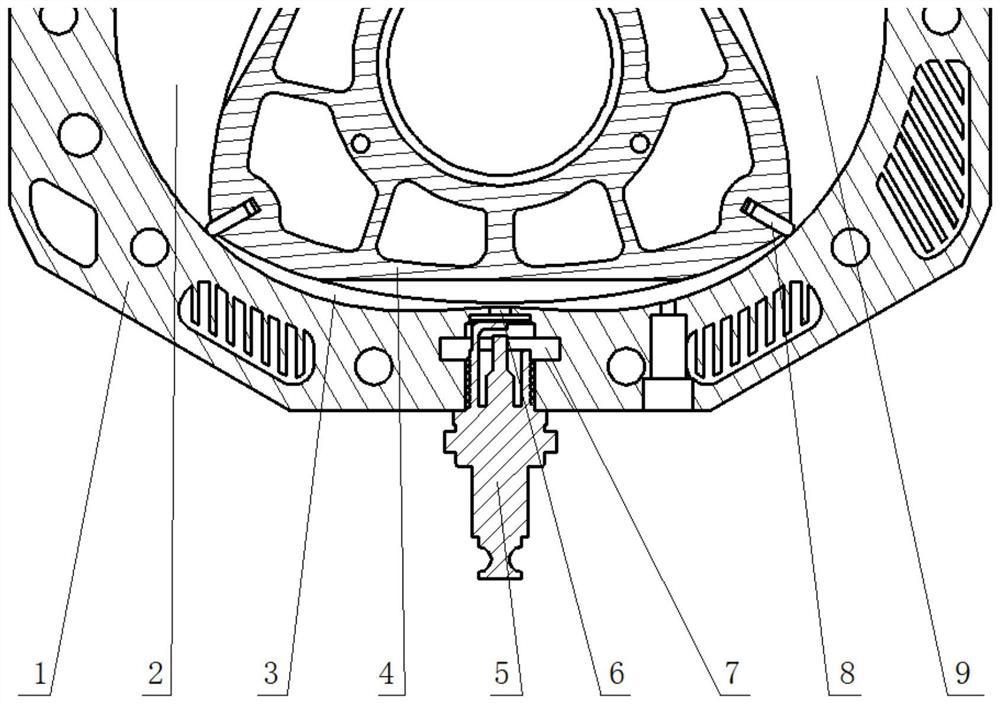
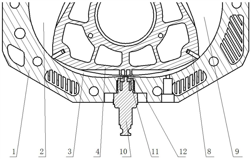
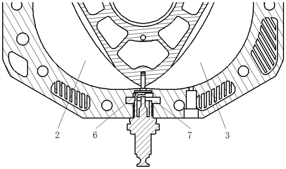
[0035] figure 1 The traditional small rotary engine spark plug ignition device shown with figure 2 The comparison of the spark plug ignition device and method in the combustion chamber of a small rotary engine shown shows that the spark plug ignition devices of the two devices have the same structure: engine cylinder 1, first working chamber 2, second working chamber ( figure 1 , 2 Moment is combustion chamber) 3, triangular rotor 4, sealing plate 8, the 3rd working chamber 9, these structures are the basic structure of small-sized rotor engine. and figure 1 The ordinary spark plug 5, the spark plug channel 6 and the ignition chamber 7 are the unique structures of the spark plug ignition device of the traditional small rotary engine; figure 2 The modified spark plug 10, bushing 11 and cathode 12 are the unique structures of the spark plug ignition device and method in the combustion chamber of a small rotary engine disclosed in this embodiment.

[0036] The modified spar...


PUM


Abstract

The invention discloses a sparking plug ignition device in a combustion chamber of a small rotary engine and a method, and belongs to the field of small rotary engines. The device provided by the invention comprises a first working chamber, a second working chamber, an ordinary sparking plug, a sparking plug channel, an ignition chamber, sealing sheets and a third working chamber, and further comprises an engine cylinder, a modified sparking plug, a modified sparking plug anode, bushings, a cathode and a triangle rotor. The sparking plug ignition device provided by the invention has the following advantages by removing the ignition chamber and the sparking plug channel: (1) energy loss is reduced and the probability of blow-by of gas between two adjacent cylinders is lowered; and (2) the compression ratio can also be improved without changing the rest of the structure, and the smaller the size of an engine, the greater the increase in the compression ratio. By improving the ignition position from the interior of the ignition chamber to the interior of the combustion chamber, the following advantages are achieved: (1) the flame propagation distance is greatly reduced, and the possibility of knocking and flame quenching of the small rotary engine is reduced; and (2) the direct contact of spark with compressed fresh gas mixture reduces the difficulty in ignition.

Description

technical field [0001] The invention relates to the composition of basic components of a small rotor engine, in particular to a spark plug ignition device and working method in a combustion chamber based on a small rotor engine, and belongs to the field of small rotor engines. Background technique [0002] With the development of micro-electro-mechanical systems (MEMS) and the introduction of a variety of miniaturized military equipment concepts, the development of micro-energy systems with small volume, light weight, high energy density, and continuous operation has become the focus of attention of various countries. Compared with traditional portable power sources, micro-engines use hydrocarbons as fuels, which have much higher energy density, stable voltage, and low cost. Therefore, micro-engines will have wide application prospects in electronic devices in various industries such as industry, agriculture, environmental protection, medical and health care, etc., and can a...

Claims


Application Information

Patent Timeline
Patent Type & Authority Patents(China)
IPC IPC(8): F02B53/12F02B55/02F02P3/00
CPCF02B53/12F02B55/02F02P3/00Y02T10/12
Inventor 刘金祥焦慧超李媛邹润白文君
Owner BEIJING INSTITUTE OF TECHNOLOGYGY
Why Eureka
Try Eureka