
Magnetic property measurement system and method for magnetic material

A magnetic material and measurement system technology, which is applied in the direction of magnetic performance measurement, magnetic field measurement by electromagnetic devices, hysteresis curve measurement, etc., can solve the problem that the filter circuit cannot be achieved, affects the accurate solution of the magnetic field strength of the magnetic circuit method, and cannot be determined intuitively The relationship between the length of the sample and other issues, to achieve the effects of small air gap, improve measurement accuracy, and low excitation power

Active Publication Date: 2019-12-06
NORTH CHINA ELECTRIC POWER UNIV (BAODING)
View PDF10 Cites 4 Cited by
  • Summary
  • Abstract
  • Description
  • Claims
  • Application Information

AI Technical Summary

Problems solved by technology

The power electronic full-bridge inverter circuit widely used in high-voltage DC transmission is actually a switching power supply. Due to the existence of parasitic inductance in the power loop of these circuits, it will lead to unavoidable overshoot and oscillation when switching
On the other hand, it is impossible for any filter circuit to achieve a completely ideal effect. As far as the H-coil method is concerned, the slight disturbance generated during the waveform switching process may be amplified and delayed in the conversion of electric-magnetic-electrical signals. Therefore, it is necessary to seek a more accurate method for determining the magnetic field strength
The magnetic circuit method is a method to solve the magnetic field strength developed based on the Ampere loop law. The key lies in the determination of the magnetic circuit length. The IEC standard provides the magnetic circuit length of the Epstein square circle, but for nanocrystals, etc. The standards for new magnetic materials have not yet been formulated, and the relationship between the effective magnetic circuit length and the sample length in a closed magnetic circuit cannot be visually determined, which affects the accurate solution of the magnetic field strength obtained by the magnetic circuit method

Method used


Image

  • Magnetic property measurement system and method for magnetic material
  • Magnetic property measurement system and method for magnetic material
  • Magnetic property measurement system and method for magnetic material

Examples


Embodiment Construction

[0045]The following will clearly and completely describe the technical solutions in the embodiments of the present invention with reference to the accompanying drawings in the embodiments of the present invention. Obviously, the described embodiments are only some, not all, embodiments of the present invention. Based on the embodiments of the present invention, all other embodiments obtained by persons of ordinary skill in the art without making creative efforts belong to the protection scope of the present invention.

[0046] The object of the present invention is to provide a system and method for measuring magnetic properties of magnetic materials, so as to improve the measurement accuracy of magnetic field strength in the process of measuring the magnetic properties of magnetic materials.

[0047] In order to make the above objects, features and advantages of the present invention more comprehensible, the present invention will be further described in detail below in conjun...


PUM


Abstract

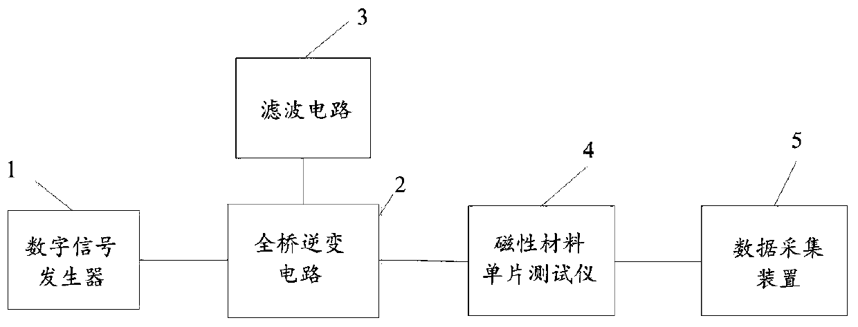
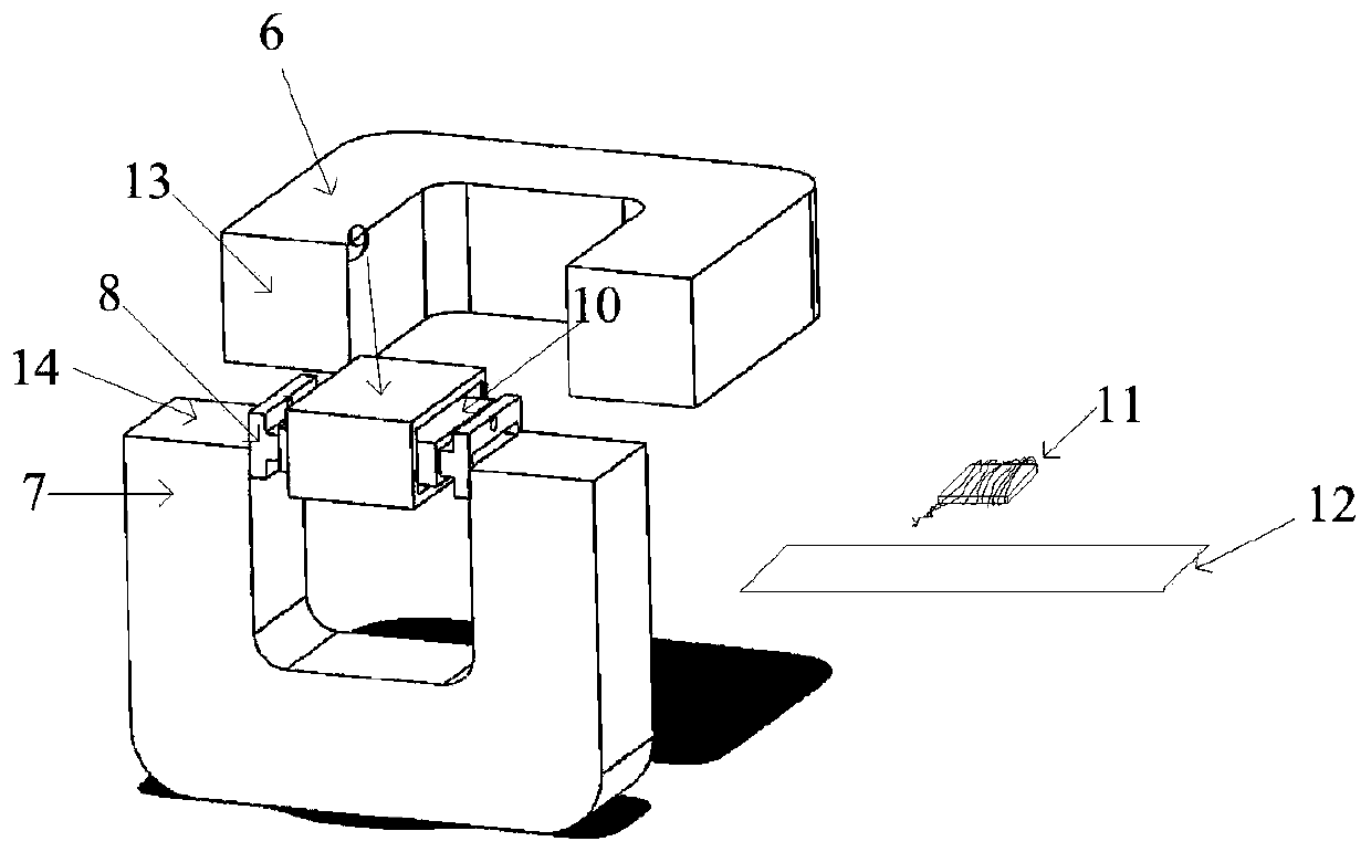
The invention provides a magnetic property measurement system and method for a magnetic material. The measurement system comprises a digital signal generator, a full bridge inverter circuit, a filtercircuit, a magnetic material monolithic tester and a data acquisition device. Four absorption capacitors of the filter circuit are connected in parallel with four switch tubes of the full bridge inverter circuit to realize coupling with the full bridge inverter circuit, so as to filter out overshoot and oscillation generated in the switching process of the switch tubes, effectively inhibit the interference of a peripheral circuit, and improve the measurement accuracy of the magnetic field intensity in the magnetic property measurement process of the magnetic material.

Description

technical field [0001] The invention relates to the technical field of electromagnetic measurement, in particular to a system and method for measuring magnetic properties of magnetic materials. Background technique [0002] As an effective method for measuring the magnetic properties of magnetic materials, single-chip tester method (SST) is usually used in conjunction with linear power supplies such as power amplifiers to explore the magnetic properties of magnetic materials under different excitation forms. This is different from the actual working conditions in which magnetic materials are used as key components of high-frequency transformers for high-voltage direct current transmission. The power electronic full-bridge inverter circuit widely used in high-voltage DC transmission is actually a switching power supply. Due to the existence of parasitic inductance in the power loop of these circuits, it will inevitably lead to overshoot and oscillation when switching. On the...

Claims


Application Information

Patent Timeline
IPC IPC(8): G01R33/12G01R33/14G01R33/06
CPCG01R33/06G01R33/12G01R33/123G01R33/14
Inventor 李琳张希蔚张岩庞舰
Owner NORTH CHINA ELECTRIC POWER UNIV (BAODING)
Learn More