Axial Magnetic Field Flywheel Pulse Synchronous Generator System

An axial magnetic field and pulse synchronization technology, which is used in the control of generators, synchronous motors with static armatures and rotating magnets, and magnetic circuits through magnetic field changes. It can solve the problem of low power density, low energy density and large volume and weight. and other problems, to achieve the effect of high power density and energy density, simple system structure and low excitation power

Active Publication Date: 2022-06-28
HARBIN INST OF TECH
View PDF14 Cites 0 Cited by
  • Summary
  • Abstract
  • Description
  • Claims
  • Application Information

AI Technical Summary

Problems solved by technology

[0006] The purpose of the present invention is to solve the problems of long shafting, low speed, low power density, low energy density, large volume and weight, and low reliability of the existing flywheel pulse generator set, so as to provide an axial magnetic field flywheel pulse synchronous generator system

Method used


Image

  • Axial Magnetic Field Flywheel Pulse Synchronous Generator System
  • Axial Magnetic Field Flywheel Pulse Synchronous Generator System
  • Axial Magnetic Field Flywheel Pulse Synchronous Generator System

Examples


specific Embodiment approach 1

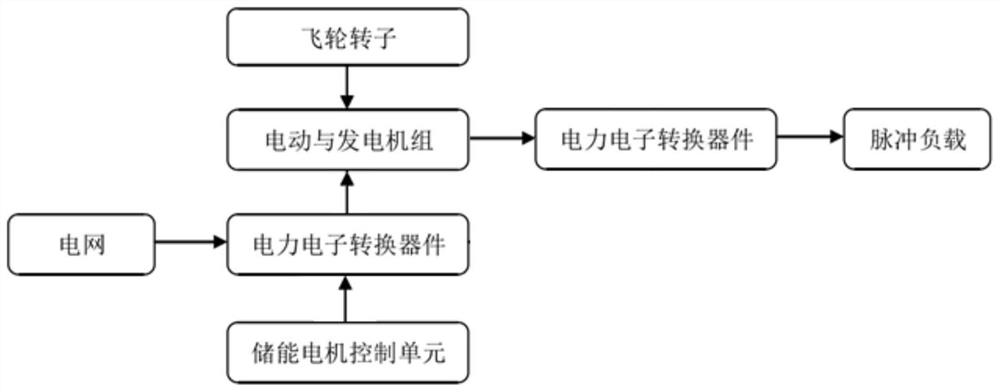
[0049] Specific implementation mode 1. Combination Figure 2 to Figure 4 Specifically describing this embodiment, an axial magnetic field flywheel pulse synchronous generator system of this embodiment includes an input inverter, an axial magnetic field embedded permanent magnet rotor synchronous motor, an output rectifier and an excitation current adjustment unit;

[0050] The output end of the input inverter is connected with the lead wire of the input power winding of the axial magnetic field embedded permanent magnet rotor synchronous motor, and the output power winding output end of the axial magnetic field embedded permanent magnet rotor synchronous motor is simultaneously connected with the AC input end of the output rectifier connected with the excitation current adjustment unit;

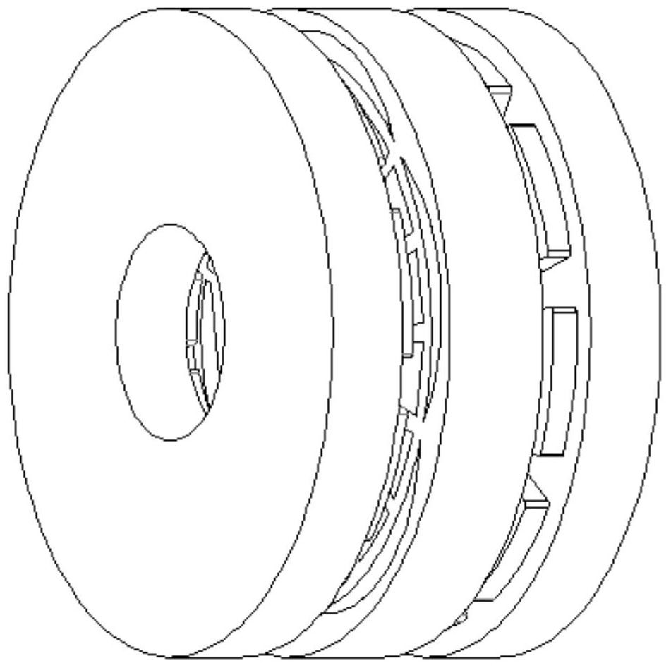
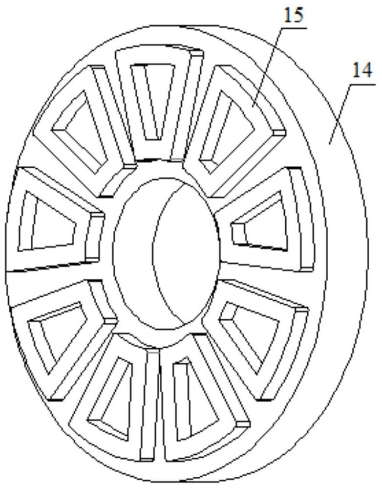
[0051] The axial magnetic field embedded permanent magnet rotor synchronous motor includes two stators and a rotor, the two stators are arranged coaxially and symmetrically on both sides of t...

specific Embodiment approach 2

[0053] Specific embodiment 2. Combination Figure 5 to Figure 7 Specifically describing this embodiment, an axial magnetic field flywheel pulse synchronous generator system of this embodiment includes an input inverter, an axial magnetic field embedded permanent magnet rotor synchronous motor, an output rectifier and an excitation current adjustment unit;

[0054] The output end of the input inverter is connected with the lead wire of the input power winding of the axial magnetic field embedded permanent magnet rotor synchronous motor, and the output power winding output end of the axial magnetic field embedded permanent magnet rotor synchronous motor is simultaneously connected with the AC input end of the output rectifier connected with the excitation current adjustment unit;

[0055] The axial magnetic field embedded permanent magnet rotor synchronous motor includes two stators and a rotor, the two stators are arranged coaxially and symmetrically on both sides of the rotor,...

specific Embodiment approach 3

[0058] Specific embodiment three, combination Figure 8 Specifically describing this embodiment, the excitation current adjustment unit in any of the above embodiments includes a controller, a multi-phase capacitor bank and a multi-phase controllable saturable reactor bank;

[0059] One end of each phase capacitor in the polyphase capacitor bank is connected to one end, and the other end is connected to the output end of the output power winding correspondingly. The polyphase capacitor bank and the polyphase controllable saturable reactor bank are connected in parallel, and the DC winding of the polyphase controllable saturable reactor bank Connected with the controller, the AC windings of the multi-phase controllable saturable reactor group are connected in a star shape.

[0060] In the figure, Qin is the input power of the excitation current adjustment unit, that is, the output power of the axial magnetic field embedded permanent magnet rotor synchronous motor output power w...


PUM


Abstract

The axial magnetic field flywheel pulse synchronous generator system belongs to the field of motor and power electronics technology. In order to solve the problem of the existing flywheel pulse generator set with long shafting and low speed, the system has low power density, low energy density, large volume and weight, and low reliability. The problem. The output end of the input inverter is connected to the lead-out line of the input power winding of the axial magnetic field embedded permanent magnet rotor synchronous motor, and the output end of the output power winding is also connected to the AC input end of the output rectifier and the excitation current adjustment unit; the motor includes two Two stators and one rotor, the two stators are coaxially and symmetrically arranged on both sides of the rotor, and there is an air gap between the stator and the rotor; each stator includes a stator core and two sets of multi-phase armature windings, and two sets of armature windings Both are embedded in the slot of the stator core or fixed on the air gap surface of the stator core, and the corresponding phases of the input power windings on the two stators are connected in series. The invention has the advantages of simple control, high efficiency, small voltage adjustment rate, strong overload capacity and high reliability.

Description

technical field [0001] The invention relates to an axial magnetic field flywheel pulse synchronous generator system, and belongs to the technical field of electric motors and power electronics. Background technique [0002] The flywheel pulse generator is a flywheel energy storage device that utilizes the large inertia of the shaft system to store energy and realizes electromechanical energy conversion by coaxial motor / generator. There are two types of flywheel energy storage devices currently in use or under development: the first is that the power level of energy storage and energy release is equivalent, and one motor can be used to alternately realize the functions of electric and power generation. The small and medium-capacity magnetic levitation flywheel energy storage system is for this The first type has the characteristics of compact structure and high efficiency, and is generally used as a flywheel battery; the second type is that the energy storage power is more th...

Claims


Application Information

Patent Timeline
Patent Type & Authority Patents(China)
IPC IPC(8): H02K16/04H02K21/24H02K7/02H02K1/2796H02K3/28H02K11/04H02K11/049H02P9/30
CPCH02K11/046H02K16/04H02K21/24H02K7/025H02K1/2793H02K3/28H02K11/04H02K11/049H02P9/30H02K2201/12H02K2213/03Y02E60/16
Inventor 寇宝泉张浩泉张艳清
Owner HARBIN INST OF TECH
Why Eureka
Try Eureka