Double excitation-winding compound-excitation double-salient brushless direct-current generator

A technology of double excitation winding and double salient motor, which is applied to synchronous generators, motors, electric vehicles, etc., can solve the problems of increased design requirements of power devices, large capacity of excitation controllers, and high cost of excitation controllers, and achieves simple design. , The effect of low excitation loss and high reliability

Active Publication Date: 2014-09-03
NANJING UNIV OF AERONAUTICS & ASTRONAUTICS
View PDF3 Cites 0 Cited by
  • Summary
  • Abstract
  • Description
  • Claims
  • Application Information

AI Technical Summary

Problems solved by technology

[0004] The excitation winding of the electrically excited double-salient pole brushless DC generator must be provided by a separate DC power supply, and its excitation power is completely provided by an external power supply. Therefore, in medium and high-power applications, the required excitation power is large, and The excitation controller required to control the excitation current has a large capacity, and the design requirements of its power devices are greatly improved, which makes the excitation controller expensive and less reliable

Method used


Image

  • Double excitation-winding compound-excitation double-salient brushless direct-current generator
  • Double excitation-winding compound-excitation double-salient brushless direct-current generator
  • Double excitation-winding compound-excitation double-salient brushless direct-current generator

Examples


specific Embodiment 1

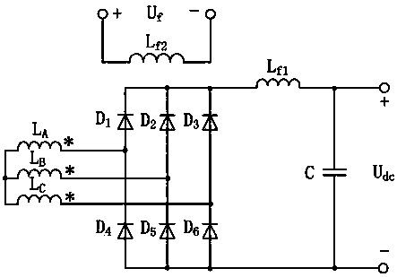
[0027] Specific embodiment 1, a schematic diagram of a double-excitation double-salient pole brushless DC generator using a full-bridge rectifier circuit is shown in Figure 3:

[0028] Rectifier circuit part: the fourth rectifier diode D 4 and the first rectifier diode D 1 series, the fifth rectifier diode D 5 and the second rectifier diode D 2 series, the sixth rectifier diode D 6 and the third rectifier diode D 3 series, the fourth rectifier diode D 4 anode of the fifth rectifier diode D 5 The anode of the sixth rectifier diode D 6 The anode connection of the first rectifier diode D 1 cathode of the second rectifier diode D 2 The cathode of the third rectifier diode D 3 the cathode connection.

[0029] L A , L B , L C The input terminals of the three-phase armature windings are connected, L A , L B , L C The output ends of the three-phase windings are respectively connected to the first rectifier diode D 1 The anode of the second rectifier diode D 2 The ano...

specific Embodiment 2

[0030] Specific embodiment two, the schematic diagram when the double-excitation winding compound-excited double-salient pole brushless DC generator adopts the common-cathode zero-type rectifier circuit is as follows Figure 4 Shown:

[0031] LA , L B , L C The input terminals of the three-phase armature windings are connected, L A , L B , L C The output ends of the three-phase armature windings are respectively connected to the first to third rectifier diodes D 1 、D 2 、D 3 The anodes of the first to third rectifier diodes D 1 、D 2 、D 3 The cathode common connection. The first set of excitation winding L f1 One end of the third rectifier diode D 3 The cathode connection of the first set of field winding L f1 The other end of the output filter capacitor C is connected to one pole, the other pole of the output filter capacitor C is connected to the input end of the A-phase armature winding, and the second set of excitation winding L f2 Separately connected to the D...

specific Embodiment 3

[0032] Specific embodiment three, the schematic diagram when the double-excitation winding double-salient pole brushless DC generator adopts a common anode zero-type rectifier circuit is as follows Figure 5 Shown:

[0033] L A , L B , L C The input terminals of the three-phase armature windings are connected, L A , L B , L C The output ends of the three-phase armature windings are respectively connected to the first to third rectifier diodes D 1 、D 2 、D 3 The cathode is connected, the first to the third rectifier diode D 1 、D 2 、D 3 anode common connection. The C pole of the output filter capacitor and the third rectifier diode D 3 The anode of the output filter capacitor C is connected to the other pole of the first set of excitation winding L f1 One end of the connection, the first set of excitation winding L f1 The other end is connected to the input end of the A-phase armature winding, and the second set of excitation winding L f2 Separately connected to th...


PUM


Abstract

The invention, which belongs to brushless generator field, discloses a double excitation-winding compound-excitation double-salient brushless direct-current generator. The double excitation-winding compound-excitation double-salient brushless direct-current generator comprises: a double excitation-winding compound-excitation double-salient motor, a rectification circuit and a filtering capacitor. An armature winding of the double excitation-winding compound-excitation double-salient motor, the rectification circuit, a first set of excitation winding of the double excitation-winding compound-excitation double-salient motor and the filtering capacitor are successively connected in series. A second set of the excitation winding of the double excitation-winding compound-excitation double-salient motor is connected with a direct current excitation power supply. Because of a self-excitation effect of the first set of the excitation winding, a generator voltage regulation rate is low and excitation power needed by control output is low. The generator is especially suitable for independent power supply systems, such as an electric automobile vehicle power generation system, an airplane power generation system and the like.

Description

technical field [0001] The invention relates to a compound excitation double salient pole brushless direct current generator with double excitation windings, and belongs to the field of brushless direct current motors. Background technique [0002] The doubly salient pole motor is a new double salient variable reluctance motor developed on the basis of the switched reluctance motor. In the early 1990s, Professor T.A.Lipo of the United States invented the permanent magnet double salient pole motor. The stator and rotor of the permanent magnet double salient pole motor are both salient pole structures, which are made of silicon steel sheets. The structure is simple, there is no winding on the rotor, and the reliability is high. High advantages, but the air gap magnetic field is difficult to adjust, so voltage regulation or constant power field weakening control is difficult. [0003] The electrically excited doubly salient motor replaces the permanent magnet with the excitat...

Claims


Application Information

Patent Timeline
Patent Type & Authority Patents(China)
IPC IPC(8): H02K19/30H02K19/36
CPCY02T10/641Y02T10/64
Inventor 张卓然钱乐严仰光
Owner NANJING UNIV OF AERONAUTICS & ASTRONAUTICS
Why Eureka
Try Eureka