Artificial hip joint with micro-dynamic function

A dynamic function and hip joint technology, applied in the field of artificial implants, can solve problems such as improper material selection, different hip joint movements, complex structures, etc., and achieve the effects of avoiding prosthesis loosening, practical novelty and operability

Pending Publication Date: 2019-12-10
何伟义
View PDF1 Cites 2 Cited by
  • Summary
  • Abstract
  • Description
  • Claims
  • Application Information

AI Technical Summary

Problems solved by technology

However, there are some problems that may not be solved in this kind of exploration, such as: 1. The structure is complex; 2. Or it can only move up and down in a straight line, which is different from the act

Method used


Image

  • Artificial hip joint with micro-dynamic function
  • Artificial hip joint with micro-dynamic function
  • Artificial hip joint with micro-dynamic function

Examples


Embodiment Construction

[0024] Hereinafter, the application of the present invention will be further described in conjunction with the accompanying drawings:

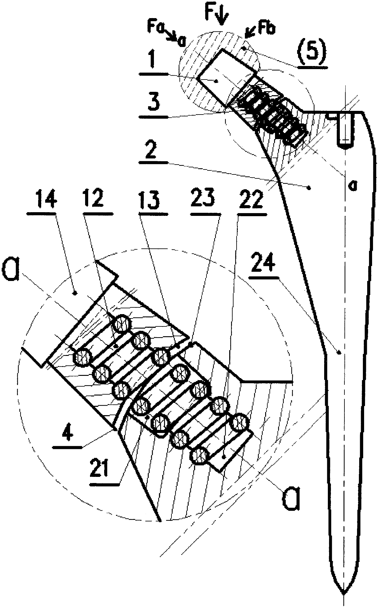
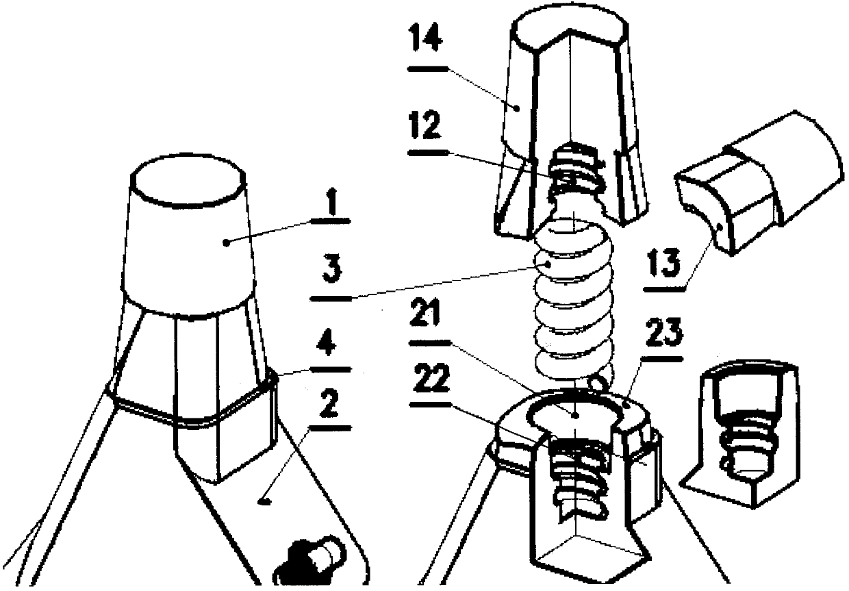
[0025] Such as figure 1 Shown is a two-dimensional schematic diagram of Embodiment 1 of the present application and its partial enlarged view. It can be seen from the figure that the artificial hip joint shown in the entire application of the present invention is divided into three parts, namely the neck 1, Handle body 2, and columnar spring 3; The artificial acetabulum (5) belonging to the external fitting is placed on the boss 14 at the upper end of the neck 1 through the tapered blind hole inside; the handle body 2 The columnar body 24 at the downward end is implanted in the femur.

[0026] From figure 1 In the partially enlarged figure shown, it can also be clearly seen that the neck 1 and the handle body 2 are not a single body, but are designed as two related ones, and are formed by the columnar spring 3. The two bodies that are flexi...


PUM


Abstract

The invention discloses an artificial hip joint with a micro-dynamic function. An artificial implant applied to a hip joint replacement surgery. The artificial hip joint with the micro-dynamic function comprises a neck, a handle body and a columnar spring for flexibly connecting the neck with the handle body. For the artificial hip joint, by utilizing the characteristics of the columnar spring, acting force, generated by movement of a human body, on a thighbone is effectively reduced, and thus the possibility of prosthesis loosening possibly causing surgery failure is reduced or avoided.

Description

technical field [0001] The application of the present invention relates to an artificial implant used in orthopedic surgery, specifically an artificial hip joint used in hip joint replacement surgery for treating hip joint diseases. Background technique [0002] Hip replacement is one of the major medical inventions that have been widely used clinically since the 1960s. The implants used, that is, artificial hip joints, have undergone various improvements and improvements: , such as assembly type and mixed type; some use mixed materials in the selection of materials, such as titanium materials and hydroxyapatite; some add stability factors to the shape, such as grooves and textures; some add various types of materials to the surface. Coatings, such as magnesium or magnesium alloys with osteocyte induction function; there are bone cement poured into the interior, etc., the purpose of which is to increase the stability of the artificial hip joint and the implanted femoral tube...

Claims


Application Information

Patent Timeline
IPC IPC(8): A61F2/36
CPCA61F2/3601A61F2/3609
Inventor 何伟义
Owner 何伟义
Why Eureka
Try Eureka