Rotary body surface robot grinding device and method

A robot and rotary body technology, which is applied to machine tools designed for grinding the rotating surface of workpieces, grinding drive devices, grinding/polishing equipment, etc., can solve the problems of high technical requirements for grinding personnel, low automation, and high labor costs. , to achieve the effect of avoiding inefficient process, improving grinding quality, avoiding vibration and shock

Active Publication Date: 2019-12-10
SHANGHAI AEROSPACE EQUIP MFG GENERAL FACTORY
View PDF5 Cites 4 Cited by
  • Summary
  • Abstract
  • Description
  • Claims
  • Application Information

AI Technical Summary

Problems solved by technology

[0002] In the production process of hardware such as metal water cups, grinding is an important process, and it is also a difficulty and pain point in the production of enterprises: first, the degree of automation of grinding is low and requires a lot of labor; second, grinding is harmful to human health. The labor cost is very high; thirdly, the technical requirements for the polishing personnel are high, and they need to be trained for a period of time before they can work. During the emergency period of production, it is difficult to temporarily expand the personnel to supplement the production capacity.

Method used


Image

  • Rotary body surface robot grinding device and method
  • Rotary body surface robot grinding device and method
  • Rotary body surface robot grinding device and method

Examples


Embodiment Construction

[0020] The present invention will be described in detail below in conjunction with the accompanying drawings and examples.

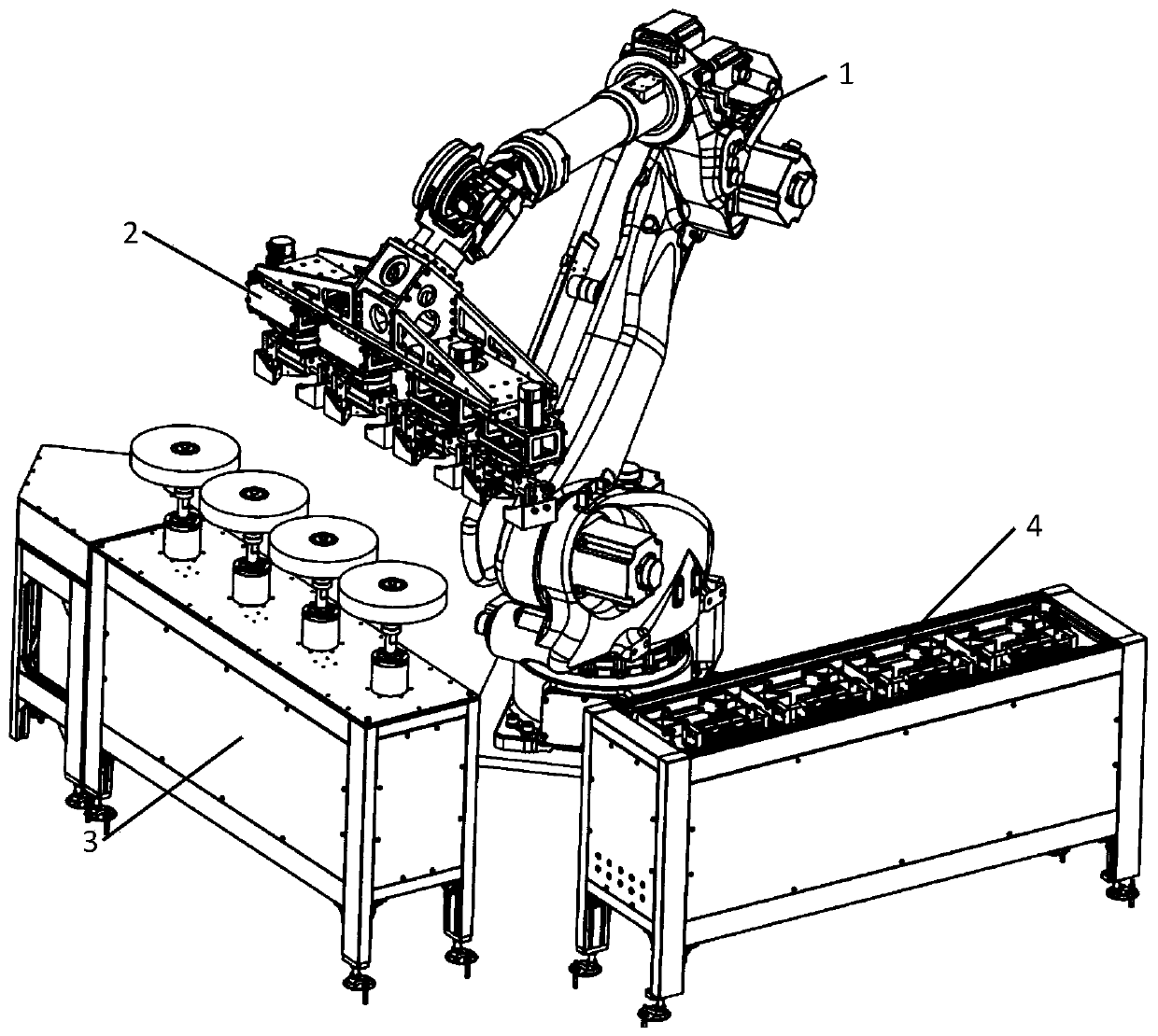
[0021] Taking grinding four workpieces at the same time as an example, a schematic diagram of a robot grinding equipment for the surface of a rotating body is as follows: figure 1 As shown, it includes: a six-degree-of-freedom industrial robot 1; four sets of compliance devices and rotary pneumatic clamps are installed at the end of the robot through connecting tooling 2; a horizontal grinding machine station 3 with four grinding heads; four sets of clamp changing devices Changing station 4.

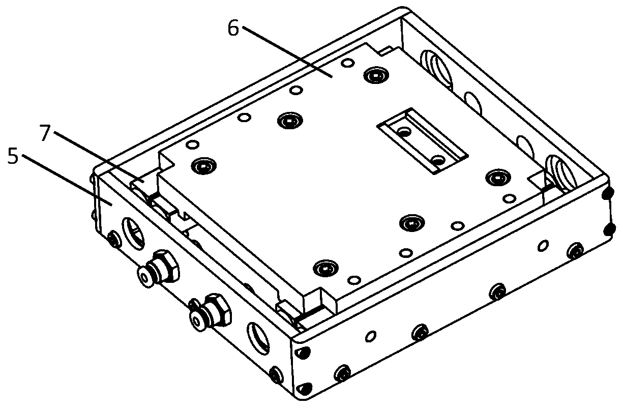
[0022] The compliance device such as figure 2 As shown: the fixed end 5 and the movable end 6 are connected by a linear guide rail 7, and the two parts can move linearly in a single direction. A cylinder is installed inside, and the force of the relative movement is controlled by adjusting the air pressure of the cylinder.

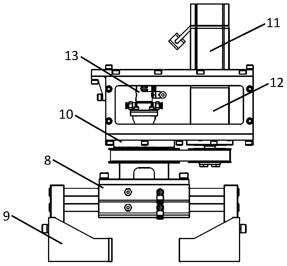
[0023] The rotary pneumatic clamp suc...


PUM


Abstract

The invention relates to a rotary body surface robot grinding and polishing device and method. According to the rotary body surface robot grinding and polishing device and method, a robot is used as an actuating mechanism to implement grinding. The device comprises the robot, softening devices, rotary pneumatic fixtures, a horizontal grinding machine and claw exchange devices. The grinding methodcomprises the following steps that S1, the robot grabs one ends of rotary bodies (workpieces) through the rotary pneumatic fixtures; S2, the robot are attached to the horizontal grinding machine according to the surface shapes of the rotary bodies, the rotary pneumatic fixtures rotate to conduct grinding on the surfaces of the rotary bodies, the grinding contact force is controlled through the softening devices, and position errors of the robot are compensated for; S3, the robot places the rotary bodies on the claw exchange devices, and the other ends of the rotary bodies are clamped through the rotary pneumatic fixtures after the claw exchange devices are turned over; and S4, the step S2 is repeated, and the remaining areas of the rotary bodies are subjected to grinding. The rotary body grinding method provided by the invention is simple, practical and applicable to surface grinding of rotary bodies such as metal cups, cylindrical containers and tube segments.

Description

technical field [0001] The patent of the present invention relates to a robot grinding equipment and method, in particular to a robot grinding equipment and method for rotating workpieces. Background technique [0002] In the production process of hardware such as metal water cups, grinding is an important process, and it is also a difficulty and pain point in the production of enterprises: first, the degree of automation of grinding is low and requires a lot of labor; second, grinding is harmful to human health. The labor cost is very high; thirdly, the technical requirements for the polishing personnel are high, and they need to be trained for a period of time before they can work. During the emergency period of production, it is difficult to temporarily expand the personnel to supplement the production capacity. [0003] The use of robots for automatic grinding of hardware is the development trend of industrial production now. It not only has high production efficiency, b...

Claims


Application Information

Patent Timeline
Patent Type & Authority Applications(China)
IPC IPC(8): B24B5/35B24B5/36B24B27/00B24B41/00B24B41/02B24B47/12
CPCB24B5/35B24B5/36B24B27/0076B24B41/005B24B41/02B24B47/12
Inventor 许腾云张秋华张春杰张瀚文
Owner SHANGHAI AEROSPACE EQUIP MFG GENERAL FACTORY
Why Eureka
Try Eureka