A rotary hydraulic jet cutting casing tool and its construction method

A technology of hydrojet and construction method, which is applied in the direction of earthwork drilling and production, wellbore/well parts, etc., and can solve the problems of forging and milling displacement blade speed, unreasonable application of drilling pressure, large changes in the performance of forging and milling mud, and forging and milling cutters. In order to reduce the risk of stuck pipe, enrich the series of permanent well sealing technology and improve the efficiency of operation

Active Publication Date: 2020-05-05
PETROCHINA CO LTD +1
View PDF11 Cites 0 Cited by
  • Summary
  • Abstract
  • Description
  • Claims
  • Application Information

AI Technical Summary

Problems solved by technology

[0003] At present, the casing forging and milling plugging method is generally used to permanently plug abandoned oil, gas and water wells. However, during the construction process, there are unreasonable selection of forging and milling blades, which affects the progress of forging and milling; The maintenance of the pump has caused complicated downhole conditions, affecting the continuity of forging and milling operations; unreasonable forging and milling displacement, blade rotation speed, applied drilling pressure, and different sizes of iron filings, which affect the normal return of iron filings and cause downhole sticking Accident; the performance of the mud for forging and milling has changed greatly, and the best chip carrying effect has not been achieved. There is a risk of drill sticking during the forging and milling process, which seriously affects the progress and efficiency of forging and milling.

Method used


Image

  • A rotary hydraulic jet cutting casing tool and its construction method
  • A rotary hydraulic jet cutting casing tool and its construction method
  • A rotary hydraulic jet cutting casing tool and its construction method

Examples


Embodiment Construction

[0036] The present invention will be further described below in conjunction with the accompanying drawings, but the protection scope of the present invention is not limited to the following description.

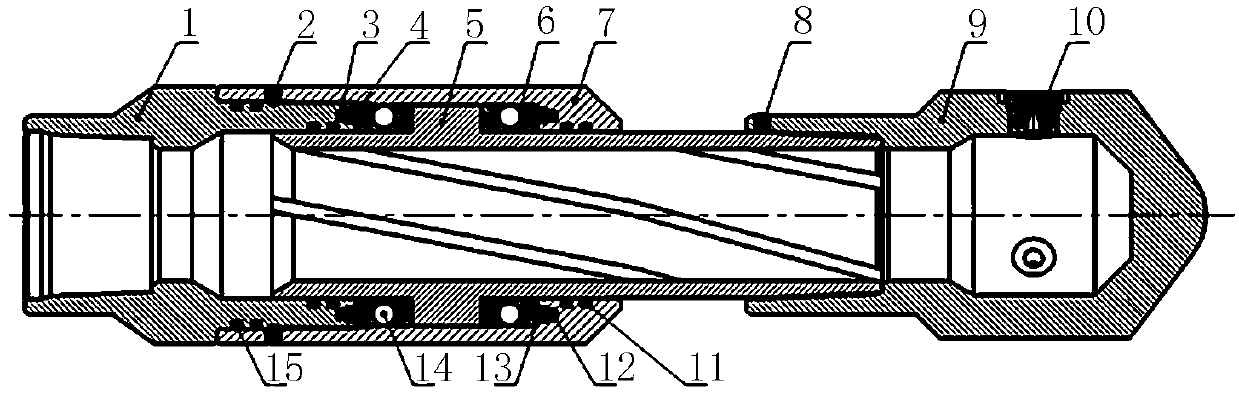
[0037] Such as figure 1 As shown, a rotary hydraulic jet cutting casing tool includes an upper joint 1, a rotating sleeve 5, an outer sleeve 7 and a rotating head 9; one end of the upper joint 1 is connected to an oil pipe 18, and the other end of the upper joint 1 One end is sleeved on the rotating sleeve 5 and inserted into the outer sleeve 7. The rotating sleeve 5 passes through the outer sleeve 7 and is inserted into the rotating head 9. The rotating sleeve 5 and the outer sleeve 7 are connected by bearings. The rotating sleeve 5 and the rotating head 9 are fixedly connected by screws, and the rotating head 9 is processed with a plurality of nozzle seats 901 along the circumferential direction, and the nozzle seats 901 deflect along the circumferential direction of the ro...


PUM


Abstract

The invention relates to a rotary type hydraulic jet cutting sleeve tool and a construction method thereof. The rotary type hydraulic jet cutting sleeve tool comprises an upper joint (1), a rotary sleeve (5), an outer sleeve (7) and a rotary head (9); one end of the upper joint (1) is connected with an oil pipe (18), the other end of the upper joint (1) is sleeved with the rotary sleeve (5) and inserted into the outer sleeve (7), the rotary sleeve (5) penetrates through the outer sleeve (7) and is inserted into the rotary head (9), the rotary sleeve (5) is connected with the outer sleeve (7) through a bearing, and the rotary sleeve (5) and the rotary head (9) are fixedly connected through screws. According to the rotary type hydraulic jet cutting sleeve tool, the sand-carrying liquid withdifferent pressure and displacement is injected into a well mouth, the rotary head of the hydraulic cutting sleeve tool is driven to rotate so as to complete operation of the hydraulic cutting sleeveand the well cementation cement ring, and the rotary type hydraulic jet cutting sleeve tool has the advantages of being high in hydraulic cutting efficiency, small in chip particle size, easy to return, small in drilling risk, free of application of drilling pressure and the like.

Description

technical field [0001] The invention relates to the field of oil and gas development equipment, in particular to a rotary hydraulic jet cutting casing tool and a construction method thereof. Background technique [0002] As the development of gas fields enters the middle and later stages, the output gradually declines or depletes, and some oil, gas, water wells or exploration wells, evaluation wells, and development wells have no potential to be tapped, or urban planning and national construction needs, in order to eliminate potential safety hazards and protect formations, To protect the environment, a permanent well closure is required. At present, the domestic solutions to permanent plugging of abandoned oil and gas wells include mechanical plugging and casing plugging in addition to conventional circulation plugging and squeeze injection sealing. The mechanical plug method refers to the purpose of sealing the oil, gas and water layers by setting mechanical plugs such as ...

Claims


Application Information

Patent Timeline
Patent Type & Authority Patents(China)
IPC IPC(8): E21B29/00
CPCE21B29/002
Inventor 马辉运张华礼喻成刚杨云山付玉坤李明杨海许定江王学强洪玉奎
Owner PETROCHINA CO LTD
Why Eureka
Try Eureka