
Inner and outer rolling wheel type rocking arm with lubricating structure

A kind of lubrication structure, roller type technology, applied in the lubrication of valve accessories, engine components, machines/engines, etc., can solve the problems of difficult rotation, concentrated force on the outer roller, cam phase deviation, etc., to increase the lubrication area, avoid early Wear, improve lubrication and heat dissipation

Pending Publication Date: 2019-12-10
GUANGXI YUCHAI MASCH CO LTD
View PDF0 Cites 3 Cited by
  • Summary
  • Abstract
  • Description
  • Claims
  • Application Information

AI Technical Summary

Problems solved by technology

However, the contact stress between the roller and the cam of the overhead camshaft structure is greater than that of the middle structure, and the roller shaft and outer roller structure have concentrated force on the outer roller and are not easy to rotate.
The conventional roller shaft, inner roller, and outer roller structure, because the working surface of the outer roller is a flat cylindrical surface, there is a situation where the force extends from the outer side to the inner side of the outer roller, and at the same time lacks effective lubricating oil circuit settings. After a long time of use, the roller and the camshaft are prone to contact fatigue wear, the valve clearance becomes larger or the cam phase deviates, which affects the performance and emission of the whole machine

Method used


Image

  • Inner and outer rolling wheel type rocking arm with lubricating structure
  • Inner and outer rolling wheel type rocking arm with lubricating structure
  • Inner and outer rolling wheel type rocking arm with lubricating structure

Examples


Embodiment Construction

[0029] In order to describe the technical content, achieved goals and effects of the present invention in detail, the following will be described in conjunction with the embodiments and accompanying drawings.

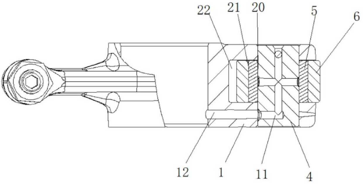
[0030] like Figure 1-7 As shown, the present invention provides an inner and outer roller rocker with a lubricating structure, including a rocker body 1 , a rocker shaft 2 , a rolling shaft 4 , an inner roller 5 and an outer roller 6 . The middle part of the rocker arm body 1 is set on the rocker arm shaft 2, and forms a rotating pair with the rocker arm shaft 2; one end of the rocker arm body 1 is provided with a relief area 3, and the rolling shaft 4 is installed on the relief area 3 through interference fit. The roller 3 is rotatably sleeved on the rolling shaft 4 through a clearance fit, and the outer roller 6 is rotatably sleeved on the inner roller 5 through a clearance fit. Wherein, the gap formed by the clearance fit between the roller shaft 4 and the inner ro...


PUM


Abstract

The invention discloses an inner and outer rolling wheel type rocking arm with a lubricating structure. The inner and outer rolling wheel type rocking arm with the lubricating structure is characterized in that a rocking arm shaft is provided with a first radial oil outflow hole and a second radial oil outflow hole communicating with a machine body main oil channel; a first oil passing channel anda second oil passing channel communicating with the first radial oil outflow hole and the second radial oil outflow hole correspondingly are arranged in a rocking arm body; a lubricating oil way is arranged in a rolling wheel shaft; one end of the lubricating oil way communicates with the first oil passing channel, and the other end of the lubricating oil way communicates with a gap between the rolling wheel shaft and an inner rolling wheel; the inner rolling wheel is internally provided with a radial oil channel; one end of the radial oil channel communicates with the gap between the rollingwheel shaft and the inner rolling wheel, and the other end of the radial oil channel communicates with a gap between an outer rolling wheel and the inner rolling wheel; and the second oil passing channel communicates with a gap between the outer rolling wheel and an avoiding area of the rocking arm body. The inner and outer rolling wheel type rocking arm with the lubricating structure makes machine oil fast flow to various gaps of rocking arm shaft parts to perform sufficient and in-time lubricating, abrasion caused by impacting and friction is reduced, and the service life of the rocking armis prolonged.

Description

technical field [0001] The invention relates to the technical field of engine components, in particular to an inner and outer roller rocker with a lubricating structure. Background technique [0002] The roller rocker arm matched with the overhead camshaft generally adopts the structure of roller shaft and outer roller or the structure of roller shaft, inner roller and outer roller. The application of the inner and outer roller structure has the advantage of reducing the load than the single outer roller structure. However, the contact stress between the roller and the cam of the overhead camshaft structure is greater than that of the middle structure, and the roller shaft and outer roller structure have concentrated force on the outer roller and are difficult to rotate. The conventional roller shaft, inner roller, and outer roller structure, because the working surface of the outer roller is a flat cylindrical surface, there is a situation where the force extends from the o...

Claims


Application Information

Patent Timeline
IPC IPC(8): F01L1/18F01M9/10
CPCF01L1/18F01M9/10
Inventor 吴定勇苏怀林覃文何化张振坤徐雪松莫昭荣周阳春
Owner GUANGXI YUCHAI MASCH CO LTD
Learn More