PV-T collector

A technology of PV-T and heat collectors, which is applied in the direction of solar heat collectors, heat insulation of solar heat collectors, and solar heat collectors using working fluids, etc., which can solve the problem of affecting the working efficiency of photovoltaic panels and insufficient heat The utilization of photovoltaic heat absorbing panels and high temperature can achieve the effect of lowering temperature, reducing heat loss and uniform medium temperature

Pending Publication Date: 2019-12-10
浙江省太阳能产品质量检验中心
View PDF9 Cites 6 Cited by
  • Summary
  • Abstract
  • Description
  • Claims
  • Application Information

AI Technical Summary

Problems solved by technology

However, there are many problems in this design: for example, due to the low heat transfer efficiency, even if there is a heat collector for heat absorption, the temperature of the photovoltaic heat absorbing plate is too high, and the efficiency decreases
[0009] Most of the current PV-T collectors use a 2-3cm air interlayer between the glass cover plate and the photovoltaic panel. On the one hand, the overall thickness of the collector will be increased, and the air interlayer is not conducive to heat transfer. If the efficiency is too low, it will affect the working efficiency of photovoltaic panels. At the same time, conventional photovoltaic panels generally leave gaps, and sunlight will pass through the gaps, and this part of the heat cannot be well utilized; in addition, conventional PV-T heat collectors The heat transfer efficiency of the device is also relatively low, which needs to be improved

Method used


Image

  • PV-T collector
  • PV-T collector
  • PV-T collector

Examples


Embodiment Construction

[0034] The following will clearly and completely describe the technical solutions in the embodiments of the present invention with reference to the accompanying drawings in the embodiments of the present invention. Obviously, the described embodiments are only some, not all, embodiments of the present invention.

[0035] Examples of the described embodiments are shown in the drawings, wherein like or similar reference numerals designate like or similar elements or elements having the same or similar functions throughout. The embodiments described below by referring to the figures are exemplary and are intended to explain the present invention and should not be construed as limiting the present invention.

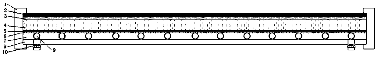
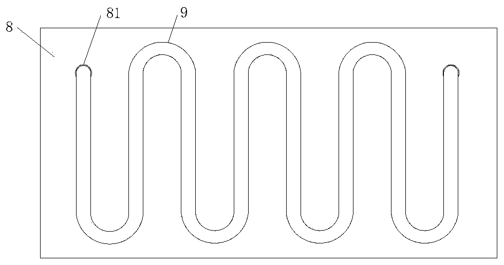
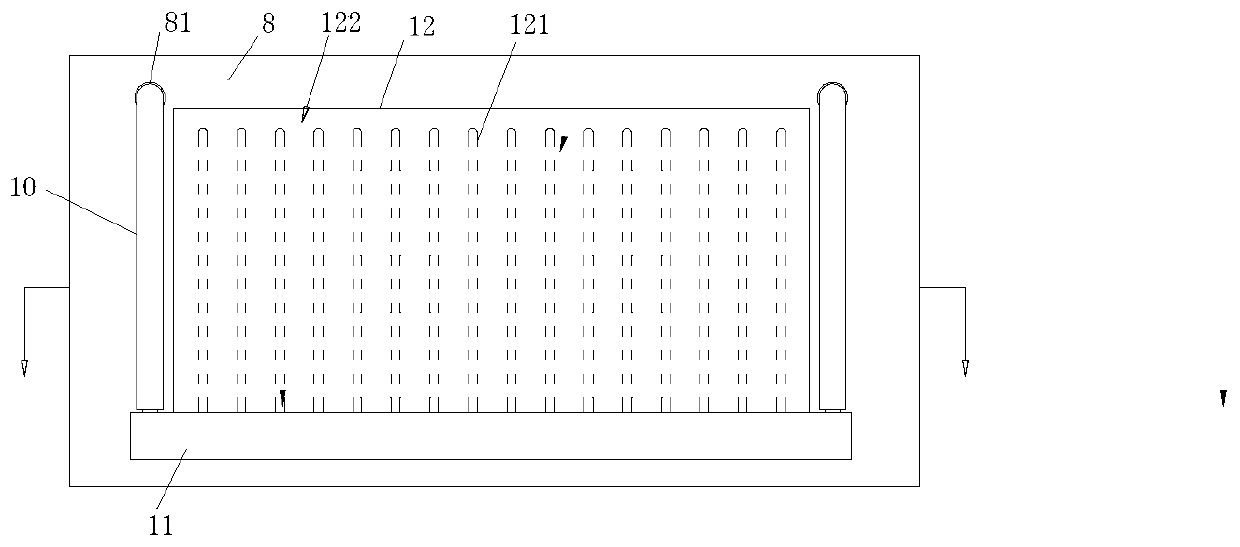
[0036] refer to figure 1 , a PV-T heat collector, including aluminum alloy frame 1, tempered glass 2 fixed in the aluminum alloy frame 1, EVA 3, photovoltaic cells 4, ultra-thin EVA 5, board core 6, insulation layer 7 and back Plate 8, tempered glass 2, EVA 3, photovoltaic ...


PUM

PropertyMeasurementUnit
thicknessaaaaaaaaaa

Abstract

The invention discloses a PV-T collector. The PV-T collector comprises an aluminum alloy frame, a toughened glass, an EVA, photovoltaic cells, an ultrathin EVA, an absorber, heat preservation layers and a back plate, wherein the toughened glass, the EVA, the photovoltaic cells, the ultrathin EVA, the absorber, the heat preservation layers and the back plate which are arranged from top to bottom are fixed in the aluminum alloy frame, the toughened glass, the EVA, the photovoltaic cells, the ultrathin EVA and the absorber are heated and laminated into a whole, the upper surface of the absorber is coated with a selective absorption coating, heat circulation devices are further arranged between the absorber and the back plate, each heat circulation device is tightly attached to the back surface of the absorber, and the heat preservation layers are arranged around the heat circulation devices in a filling mode. According to the PV-T collector, the toughened glass, the EVA, the photovoltaiccells, the ultrathin EVA and the absorber are subjected to hot pressing into a whole, an air layer is not reserved, meanwhile, the heat transfer speed of the photovoltaic cells to the absorber can beeffectively improved by adopting the ultrathin EVA, the heat transfer speed is higher than that of a traditional EVA, the heat resistance is reduced, the working temperature of the cells is effectively reduced, the power generation efficiency is improved, meanwhile, a heat exchange device is arranged, and the heat exchange device can convert the residual light energy into heat energy of the heat exchange medium.

Description

technical field [0001] The invention relates to the technical field of solar heat collectors, in particular to a PV-T heat collector integrating power generation and hot water production. Background technique [0002] In recent years, with the increasingly prominent environmental problems and energy problems, new energy technologies have attracted more and more attention in the world today. Solar photovoltaic technology has emerged as a new type of pollution-free power generation technology, but efficiency issues have always been the bottleneck restricting the development of photovoltaic technology. , where temperature is one of the main factors restricting the efficiency of photovoltaic panels. PVT collectors combine traditional solar collectors with photovoltaic cells to generate hot water while cooling photovoltaic cells to improve electrical efficiency. Moreover, this heat collecting device is safe, energy-saving and pollution-free, and is favored by people. [0003] I...

Claims


Application Information

Patent Timeline
Patent Type & Authority Applications(China)
IPC IPC(8): F24S10/55F24S10/70F24S70/225F24S80/65H02S40/44H02S40/42
CPCF24S10/55F24S10/70F24S70/225F24S80/65H02S40/42H02S40/44Y02E10/44Y02E10/50Y02E10/60
Inventor 凌德利韩雷涛沈斌沈桥袁逸中
Owner 浙江省太阳能产品质量检验中心
Why Eureka
Try Eureka