A cooling cycle system

A circulation system and cold-carrying technology, which is applied in the direction of refrigerators, refrigeration components, refrigeration and liquefaction, etc., can solve the problems of lack of reliable low-flow low-temperature circulation pumps, etc., and achieve the effect of easy distribution

Active Publication Date: 2021-09-17
TECHNICAL INST OF PHYSICS & CHEMISTRY - CHINESE ACAD OF SCI
View PDF6 Cites 0 Cited by
  • Summary
  • Abstract
  • Description
  • Claims
  • Application Information

AI Technical Summary

Problems solved by technology

However, due to the lack of reliable and commercial low-flow low-temperature circulating pumps in the temperature range below -60°C, it is not feasible to use the method of pumping brine in the low-temperature range

Method used


Image

  • A cooling cycle system
  • A cooling cycle system
  • A cooling cycle system

Examples


Embodiment 1

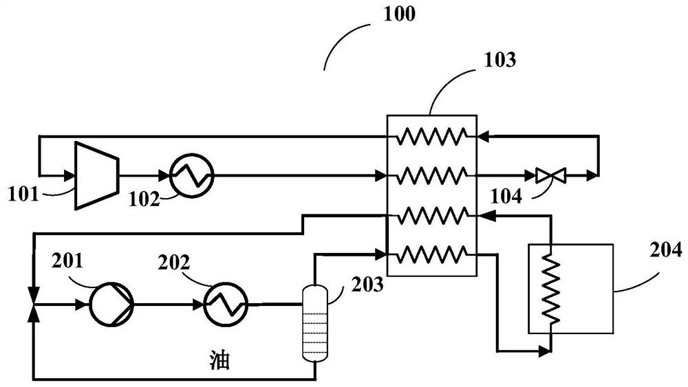
[0023] see figure 1 , is a schematic structural diagram of a load-cooling cycle system provided by Embodiment 1 of the present invention. For the convenience of description, only the parts related to the embodiment of the present invention are shown, and the details are as follows.

[0024] The load cooling cycle system 100 provided by the present invention includes: a mixed working medium refrigeration cycle circuit and a load cooling cycle circuit; the mixed working medium refrigeration circuit includes a mixed working medium compressor (101), a mixed working medium condenser (102), regenerative heat exchanger (103), mixed working medium throttle valve (104); the brine-cooled circulation loop includes brine-driven pump (201), brine condenser (202), brine precision oil separation device (203) and user side (204); wherein:

[0025] The high-pressure refrigerant outlet of the mixed working medium compressor (101) is connected to the high-pressure refrigerant inlet of the mixed...

Embodiment 2

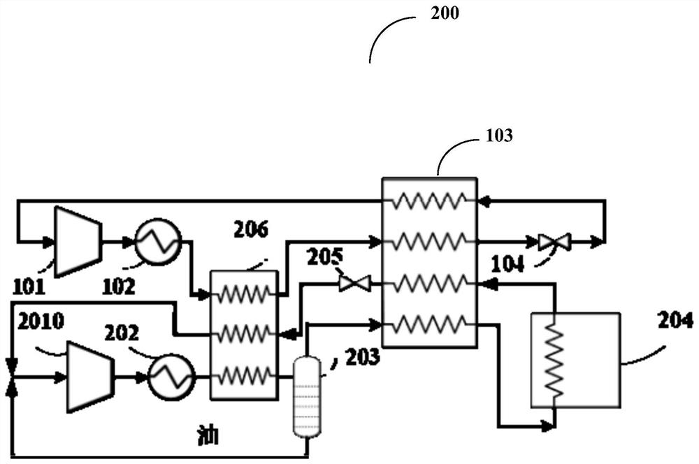
[0031] see figure 2 , is a schematic structural diagram of a load-cooling cycle system provided by Embodiment 2 of the present invention. For the convenience of description, only the parts related to the embodiment of the present invention are shown, and the details are as follows.

[0032] A cooling cycle system 200 provided by the present invention includes: a mixed working medium refrigeration cycle and a cooling cycle; the mixed working medium refrigeration circuit includes a mixed working medium compressor (101), a mixed working medium condenser (102 ), a recuperative heat exchanger (103), a mixed working medium throttle valve (104); Refrigerant precooling heat exchanger (206), brine precision oil separator (203) and user side (204); where:

[0033] The high-pressure refrigerant outlet of the mixed working medium compressor (101) is connected to the high-pressure refrigerant inlet of the mixed working medium condenser (102), and the high-pressure refrigerant outlet of t...


PUM


Abstract

The cooling cycle system provided by the present invention includes: a mixed working medium refrigeration cycle circuit and a cooling cycle circuit; the mixed working medium refrigeration circuit includes a mixed working medium compressor (101), a mixed working medium condenser (102), a return heat exchanger (103), mixed working medium throttle valve (104); the brine circulation loop includes brine driven pump (201), brine condenser (202), brine precision oil separator (203) and the user side (204), the load-cooling cycle system provided by the present invention uses the normal cooling cycle of pure or mixed working fluids with a low freezing point as the load-cooling cycle, and is driven by a high-reliability normal cooling temperature zone driving element , avoiding the use of low-reliability low-temperature circulating pumps, which can realize remote transfer of cooling capacity at ‑60°C or even in the liquid nitrogen temperature zone, and the refrigerant loaded on the user side is in a liquid phase state, easy to distribute evenly, and is especially suitable for split-type users Where low temperature is required.

Description

technical field [0001] The invention relates to the technical field of load cooling, in particular to a load cooling cycle system. Background technique [0002] Cooling technology is often used in the field of central air conditioning and industrial refrigeration, and is rarely used at low temperatures. The traditional cooling cycle is to make the refrigerant cool down in the evaporator first, and then pumped to the object to be cooled. There is only a cooling capacity transfer function, and the refrigerant itself has no cooling effect. At present, in the fields of scientific research, medical treatment, pharmaceuticals, and industrial production, the refrigeration temperature in these occasions needs to be below -60°C or even reach the temperature of liquid nitrogen, and at the same time, there are requirements for vibration and noise, high safety and reliability, such as low-temperature cold therapy, low-temperature refrigerator , low-temperature cold storage, low-tempera...

Claims


Application Information

Patent Timeline
Patent Type & Authority Patents(China)
IPC IPC(8): F25B41/40F25B43/02F28D20/00
CPCF25B43/02F28D20/0034F25B41/40Y02E60/14
Inventor 郭浩公茂琼
Owner TECHNICAL INST OF PHYSICS & CHEMISTRY - CHINESE ACAD OF SCI
Why Eureka
Try Eureka