Supercharge Your Innovation With Domain-Expert AI Agents!

Optical fiber ultrasonic sensor

An ultrasonic and sensor technology, applied in the field of fiber optic ultrasonic sensors, can solve the problems of sensor operating point drift, linearity drop, signal distortion, etc., and achieve the effect of reducing temperature interference factors, simple structure, and ensuring temperature self-stabilization mechanism

Inactive Publication Date: 2019-12-10
INST OF ELECTRONICS CHINESE ACAD OF SCI
View PDF8 Cites 4 Cited by
  • Summary
  • Abstract
  • Description
  • Claims
  • Application Information

AI Technical Summary

Problems solved by technology

[0004] Existing fiber-optic ultrasonic sensors are limited in practical applications due to temperature cross-interference issues
Especially for interferometric high-sensitivity fiber optic ultrasonic sensors, sudden temperature changes in the actual measurement environment in a short period of time will cause the sensor's operating point to drift, resulting in a series of problems such as reduced sensitivity of fiber optic ultrasonic sensors, signal distortion, and linearity degradation.

Method used

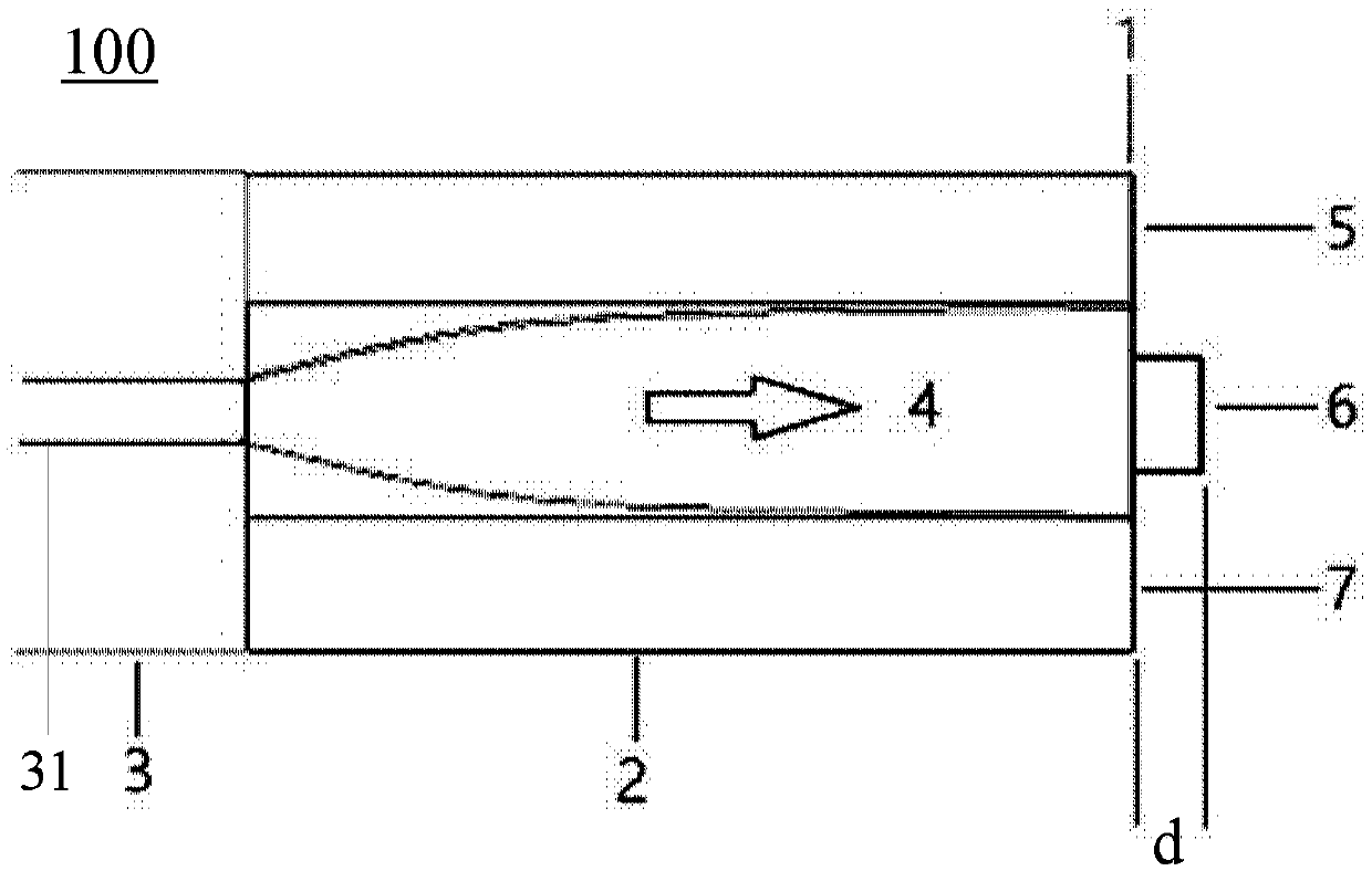
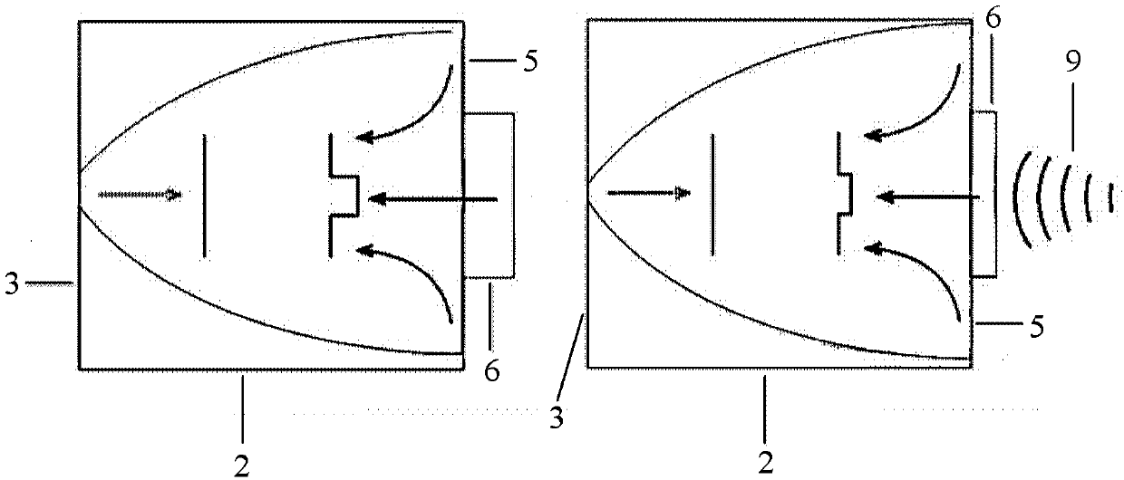
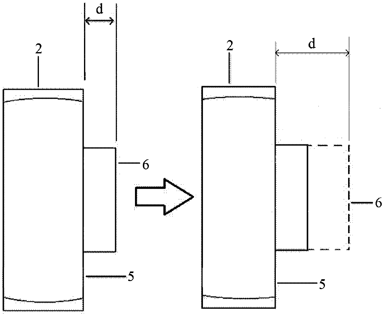

Image

  • Optical fiber ultrasonic sensor
  • Optical fiber ultrasonic sensor
  • Optical fiber ultrasonic sensor

Examples


Embodiment Construction

[0023] In order to make the object, technical solution and advantages of the present invention clearer, the present invention will be described in further detail below in conjunction with specific embodiments and with reference to the accompanying drawings. It should be noted that, in the drawings or descriptions of the specification, similar or identical parts all use the same figure numbers. Implementations not shown or described in the accompanying drawings are forms known to those of ordinary skill in the art. Additionally, while illustrations of parameters including particular values ​​may be provided herein, it should be understood that the parameters need not be exactly equal to the corresponding values, but rather may approximate the corresponding values ​​within acceptable error margins or design constraints. The directional terms mentioned in the embodiments, such as "upper", "lower", "front", "rear", "left", "right", etc., are only referring to the directions of the...


PUM


Abstract

The invention discloses an optical fiber ultrasonic sensor which comprises a single-mode optical fiber which is used for transmitting the incident light; a self-focusing optical fiber which is used for expanding and collimating the incident light transmitted by the single-mode optical fiber so as to emit the parallel light beams; a phase modulation plate which is formed on the end surface of the self-focusing optical fiber, and comprises an ultrasonic sensing surface located at the central part and a fixed reflecting surface located at the peripheral part, wherein the ultrasonic sensing surface protrudes outwards from the fixed reflecting surface by 1 / 8 of the wavelength of the incident light, the ultrasonic sensing surface and the fixed reflecting surface are configured to modulate the phases of the central part and the peripheral part of the parallel light beam respectively, so that the parallel light beams of the central part and the peripheral part are reflected by the phase modulation plate to generate the self-dual-beam interference.

Description

technical field [0001] Embodiments of the present invention relate to the technical field of optical fiber sensing, in particular to an optical fiber ultrasonic sensor. Background technique [0002] Optical fiber ultrasonic sensing technology is a new type of sensing technology developed in recent years. Compared with traditional PVDF (piezoelectric film) sensors, it has the advantages of safety, small size, light weight, and multi-point simultaneous measurement. , The military field is of great significance. [0003] Optical fiber ultrasonic sensing technology includes three types: grating ultrasonic sensing technology, intensity ultrasonic sensing technology and interference ultrasonic sensing technology. Among them, the interferometric ultrasonic sensing technology is based on the change of optical path difference caused by ultrasonic waves to optical fiber interference. Compared with the other two technologies, the interferometric optical fiber sensing technology not o...

Claims


Application Information

Patent Timeline
Patent Type & Authority Applications(China)
IPC IPC(8): G01H9/00
CPCG01H9/004
Inventor 高然祁志美张萌颖
Owner INST OF ELECTRONICS CHINESE ACAD OF SCI
Features
  • R&D
  • Intellectual Property
  • Life Sciences
  • Materials
  • Tech Scout
  • Unparalleled Data Quality
  • Higher Quality Content
  • 60% Fewer Hallucinations
Learn More