
A cable temperature detection system and a wireless temperature sensor used in the system

A wireless temperature and detection system technology, applied in the application of thermometers, thermometer parts, thermometers, etc., can solve the problems of low infrared penetration, high sensor cost, long optical fiber length, etc., to achieve strong transmission capacity and reduce power consumption. Consumption, the effect of improving the service life

Active Publication Date: 2021-01-08
上海洛霖能源互联网技术合伙企业(有限合伙) +1
View PDF6 Cites 0 Cited by
  • Summary
  • Abstract
  • Description
  • Claims
  • Application Information

AI Technical Summary

Problems solved by technology

[0003] Now the monitoring of cable temperature generally includes infrared temperature measurement and optical fiber communication temperature measurement, wireless temperature measurement and other methods. Since the cable may be almost soaked in water, the penetration of infrared rays in water is extremely low, so infrared temperature measurement is only used Suitable for overhead cables, but powerless for cables laid underground
For optical fiber communication, because the temperature measurement node is too large, the number of optical fibers is also very large, the length of the optical fiber is also very long, there are problems such as high sensor cost, and difficult maintenance. Therefore, the optical fiber communication temperature measurement method is only suitable for different temperature measurement points. There are many and concentrated occasions, and urban power supply cables have the characteristics of wide distribution and many temperature measurement points. Obviously, the optical fiber communication temperature measurement method has great limitations. For wireless temperature measurement, the current applications are relatively mature. For overhead cable temperature measurement, the temperature sensor is generally arranged at the joint, and the temperature signal is converted into an electrical signal, and then transmitted to the host computer through a certain frequency, and the host computer converts the received electrical signal into temperature to implement temperature monitoring.
[0004] The above-mentioned wireless temperature measuring device is difficult to use in underground cables, mainly because the underground cables may be soaked in water, which not only requires the sensor itself to be waterproof, but also requires that there is no water at the contact position between the sensor and the cable, or that the water at this position cannot communicate with the outside world. The water can easily exchange heat to prevent the temperature generated by the cable from being taken away by the water, causing the problem of inaccurate testing
At the same time, the underground cable may be twisted because it is in a free state. It is difficult for us to find the corresponding position of each core on the outside of the cable, which also brings problems to the installation of the sensor. Corresponding wire cores cause temperature measurement errors; on the other hand, because the cable is soaked in water, the water depth may reach about 2m, and the radio wave attenuation is very large in the water, which is also not encountered in the temperature measurement of overhead cables and switch cabinets. new subject of

Method used


Image

  • A cable temperature detection system and a wireless temperature sensor used in the system
  • A cable temperature detection system and a wireless temperature sensor used in the system
  • A cable temperature detection system and a wireless temperature sensor used in the system

Examples


Embodiment Construction

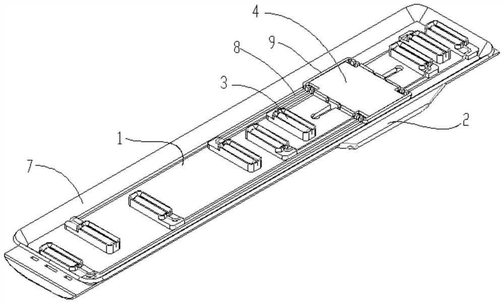
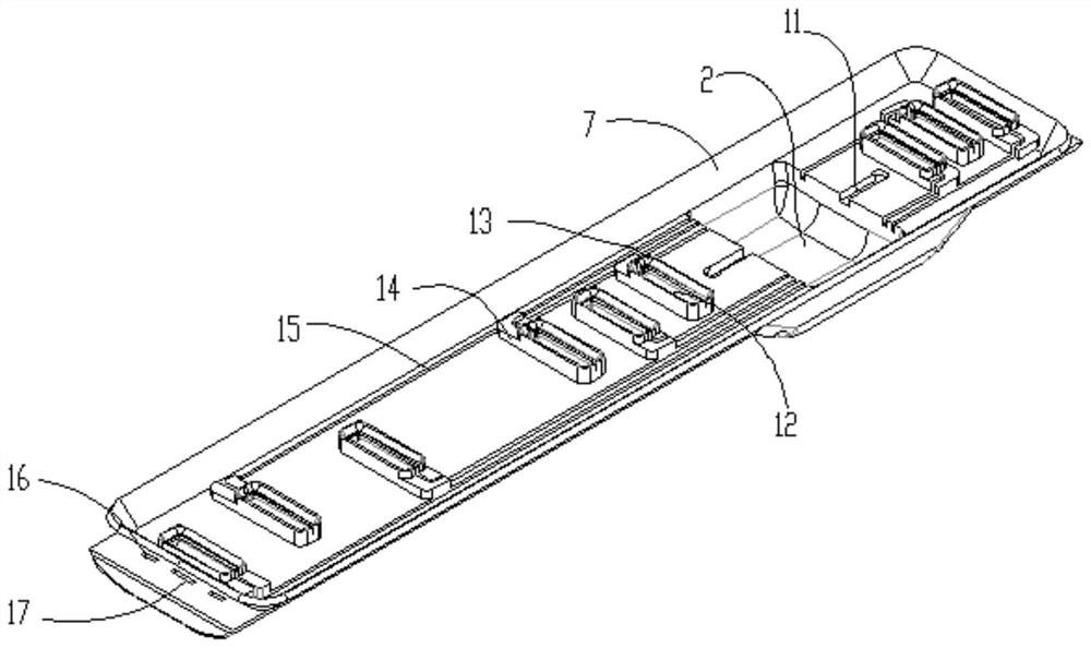
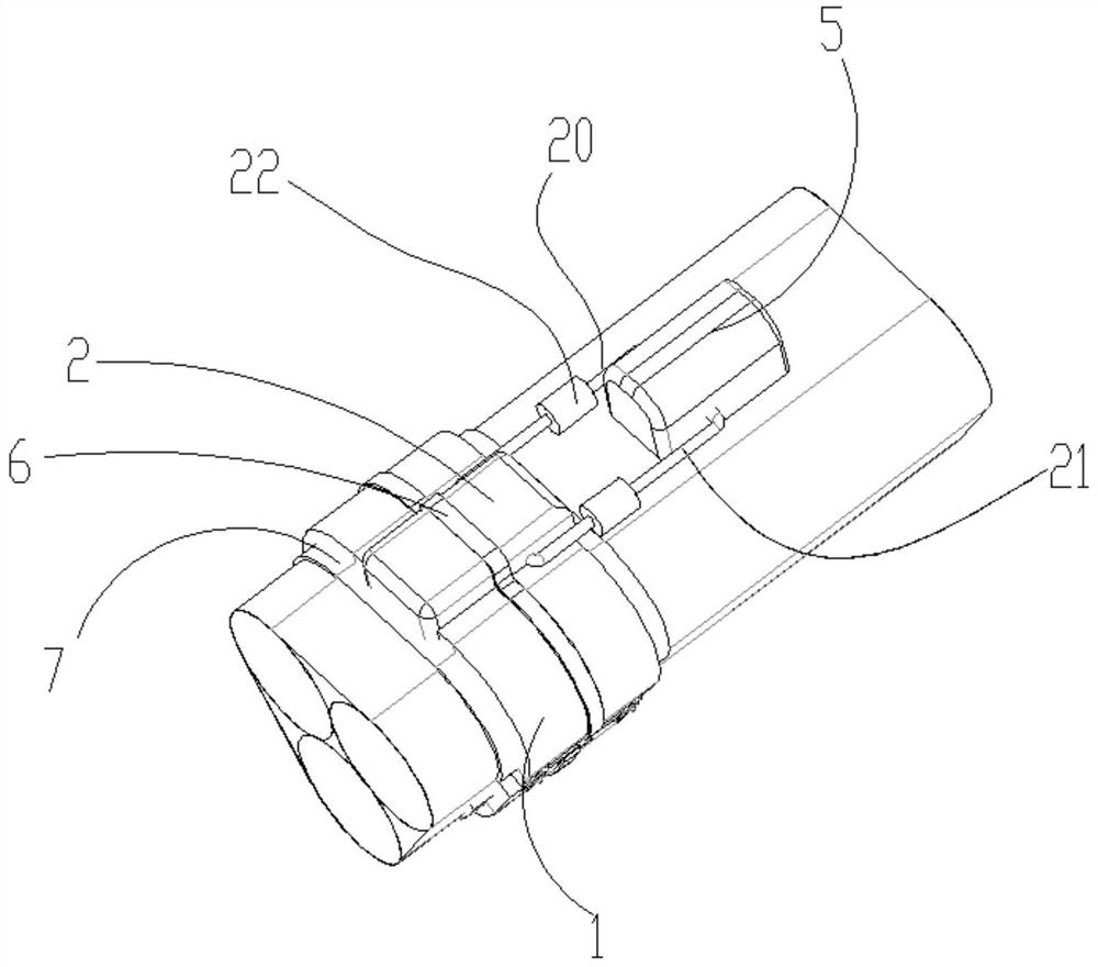
[0035] refer to Figure 1 to Figure 7 A cable temperature detection system and a wireless temperature sensor used in the system are shown, including a receiving node, a wireless gateway / base station, a wireless temperature sensor and a cloud, and wireless communication is used between the receiving node and the wireless temperature sensor Two-way data communication, wireless communication is used between the receiving node and the wireless gateway / base station for two-way data communication, the wireless temperature sensor is composed of an elastic strap 1, a temperature measuring probe 3, an electronic warehouse 2, a fixed power supply 5, and a data acquisition System, data processing system, data transceiving system and antenna 10. The wireless temperature sensor perceives the temperature of the cable through the temperature measuring probe 3, and converts it into an electrical signal through the data acquisition system and data processing system. According to the requirement...


PUM


Abstract

The invention discloses a cable temperature detection system and a wireless temperature sensor for the system. The system comprises a receiving node, a wireless gateway / base station, a wireless temperature sensor and a cloud; bidirectional data communication is carried out between the receiving node and the wireless temperature sensor in a wireless communication mode; bidirectional data communication is carried out between the receiving node and the wireless gateway / base station in a wireless communication mode; the wireless temperature sensor is composed of an elastic watchband, a temperaturemeasuring probe, an electronic bin, a fixed power supply, a data acquisition system, a data processing system, a data transceiving system and an antenna. The wireless temperature sensor senses the temperature of the cable through the temperature measuring probe; the temperature is converted into an electric signal through the data acquisition system and the data processing system, then the electric signal is transmitted to the receiving node through the antenna of the data transceiving system, the receiving node transmits the electric signal to the wireless gateway and the base station through Lora and NB-IoT communication modes, and finally the electric signal is transmitted to the cloud, so that the purpose of temperature monitoring is achieved.

Description

technical field [0001] The invention relates to a cable temperature detection system and a wireless temperature sensor used in the system. Background technique [0002] In the power industry, due to the aging of materials and other reasons, it will cause problems such as excessive local resistance or partial discharge, which will cause the temperature of the faulty part to rise, cause the aging of cables or connectors to accelerate, and cause fires in severe cases; at the same time, for the beauty of the city, gradually Aerial cables are laid underground, making troubleshooting more difficult. Especially in coastal cities, where the groundwater level is high and cables are almost submerged in water, troubleshooting is even more difficult. Generally, the precursor to cable failure is abnormal temperature, so the monitoring of cable temperature becomes very critical. [0003] Now the monitoring of cable temperature generally includes infrared temperature measurement and optic...

Claims


Application Information

Patent Timeline
Patent Type & Authority Patents(China)
IPC IPC(8): G01K13/00G01K1/024H04W4/38H04W52/02
CPCG01K1/024G01K1/026G01K13/00G01K2219/00H04W52/0229H04W4/38Y02D30/70
Inventor 张淼林李轶晨牟英峰
Owner 上海洛霖能源互联网技术合伙企业(有限合伙)
Learn More