Optical integration device and circulator

A technology for devices and light receiving components, applied in the field of optical fiber communication, can solve the problems of damage to the light emission group, reduce the luminous efficiency, etc., and achieve the effect of good isolation

Active Publication Date: 2019-12-10
ZHUHAI FTZ OPLINK COMM +1
View PDF11 Cites 8 Cited by
  • Summary
  • Abstract
  • Description
  • Claims
  • Application Information

AI Technical Summary

Problems solved by technology

However, when the laser is output from the optical emission group, the laser energy is relatively high. If the isolation is not large enough, the reverse laser reflected from the optical fiber interface will still have relatively large energy, which will have a great impact on the laser signal source of the optical emission group. Large impact, reduce luminous efficiency or even damage the light emitting group

Method used


Image

  • Optical integration device and circulator
  • Optical integration device and circulator
  • Optical integration device and circulator

Examples


Embodiment Construction

[0020] While the invention may readily manifest in different forms of embodiments, only a few specific embodiments have been shown in the drawings and will be described in detail in this specification, with the understanding that the specification should be considered as the These are exemplary illustrations of the principles of the invention and are not intended to limit the invention to what is described herein.

[0021] Thus, a feature indicated in this specification will be used to describe one of the features of an embodiment of the invention, not to imply that every embodiment of the invention must have the described feature. Furthermore, it should be noted that this specification describes a number of features. Although certain features may be combined to illustrate possible system designs, these features may also be used in other combinations not explicitly described. Thus, the illustrated combinations are not intended to be limiting unless otherwise stated.

[0022]...


PUM


Abstract

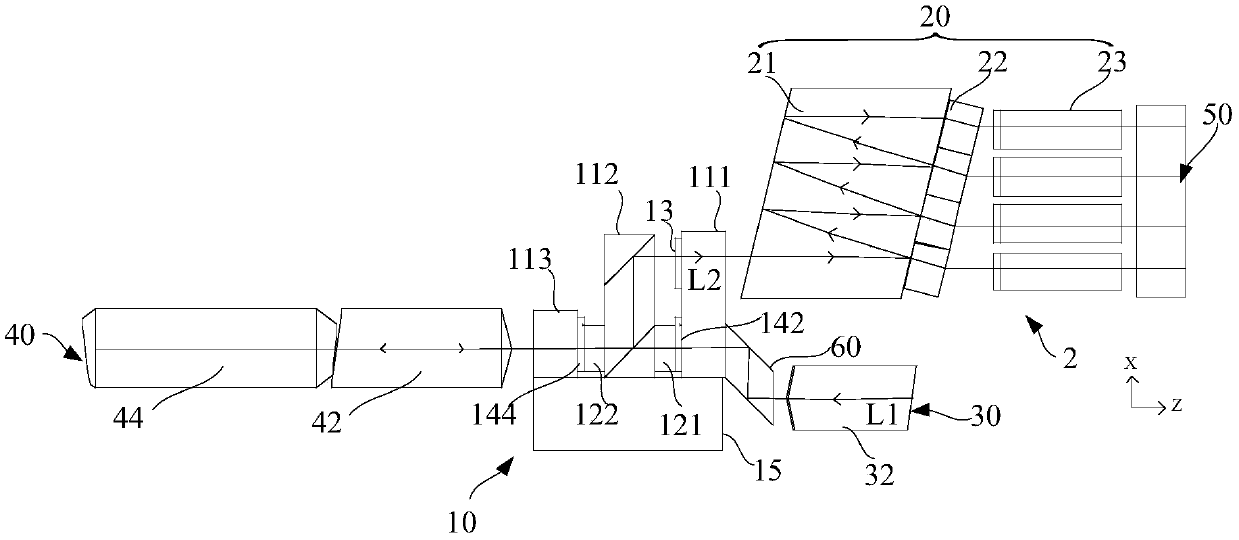
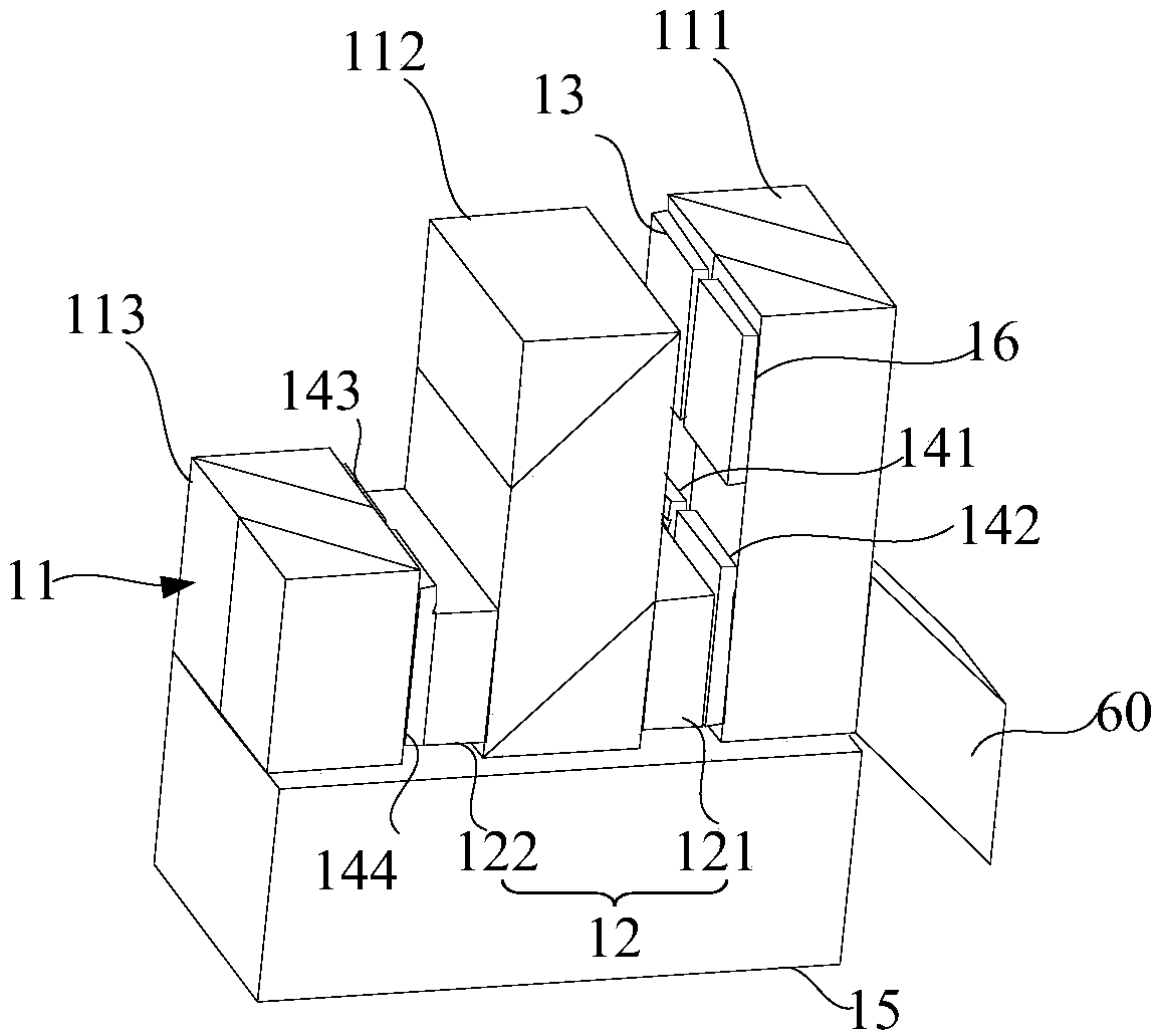
The invention provides an optical integration device and a circulator. The optical integration device comprises the circulator, an input and output optical port located at one side of the circulator,and an optical input port and an optical output port which are located at the other side of the circulator. The circulator comprises a first polarization splitting prism, a second polarization splitting prism and a third polarization splitting prism, a first Faraday rotating piece is arranged between the first polarization splitting prism and the second polarization splitting prism, and a second Faraday rotating sheet is arranged between the second polarization splitting prism and the third polarization splitting prism. According to the present invention, the reverse light entering from the input and output light port is outputted to the light input port after being isolated twice by the first Faraday rotation sheet and the second Faraday rotation sheet, so that the influence on a laser signal source can be effectively reduced. The reverse light entering from the light output port only passes through the second Faraday rotation sheet, is isolated once, and is outputted to the input / output light port, so that the isolation requirement can be met, and the cost can be reduced.

Description

technical field [0001] The invention relates to the technical field of optical fiber communication, in particular to an optical integration device and a circulator used therein. Background technique [0002] Chinese patent CN205229520U discloses a single-fiber bidirectional BOSA structure. The single-fiber bidirectional BOSA structure includes an optical transmitting group and an optical receiving group, an array circulator group, a wavelength division multiplexing / demultiplexing group, and an optical fiber interface. Several first optical signals emitted by the optical transmitting group are transmitted to the wavelength division multiplexing / demultiplexing group through the array circulator group, and then multiplexed into one optical signal and transmitted to the optical fiber interface for transmission. One optical signal output from the optical fiber interface is transmitted to the wavelength division multiplexing / demultiplexing group, demultiplexed into several second ...

Claims


Application Information

Patent Timeline
Patent Type & Authority Applications(China)
IPC IPC(8): G02B6/27G02B6/42
CPCG02B6/2746G02B6/4208G02B6/4213G02B6/4215
Inventor 吕海峰陈达鑫黄坚龙徐燕
Owner ZHUHAI FTZ OPLINK COMM
Why Eureka
Try Eureka