Pollutant solid remover spraying device for branch tube
What is Al technical title?
Al technical title is built by PatSnap Al team. It summarizes the technical point description of the patent document.
A spraying device and removal agent technology, which is applied in liquid spraying device, spraying device, gas treatment, etc., can solve the problems that pollutants easily enter the external air, the diffusion effect of the direct nozzle is not very good, and the diffusion area is reduced.
Pending Publication Date: 2019-12-13
BEIJING SPC ENVIRONMENT PROTECTION TECH
View PDF0 Cites 0 Cited by
Summary
Abstract
Description
Claims
Application Information
AI Technical Summary
This helps you quickly interpret patents by identifying the three key elements:
Problems solved by technology
Method used
Benefits of technology
Problems solved by technology
And existing sorbent\absorbent injection device generally adopts straight pipes to be directly inserted into the flue, and the nozzle of the injection device adopts a single row of straight nozzles, the diffusion effect of the straight nozzles is not very good, and the injected sorbent\absorbent cannot It completely covers the flow surface of the flue gas, and under
Method used
Image
Click on the blue label to locate the original text in one second.
Reading with bidirectional positioning of images and text.
Examples
Embodiment 1
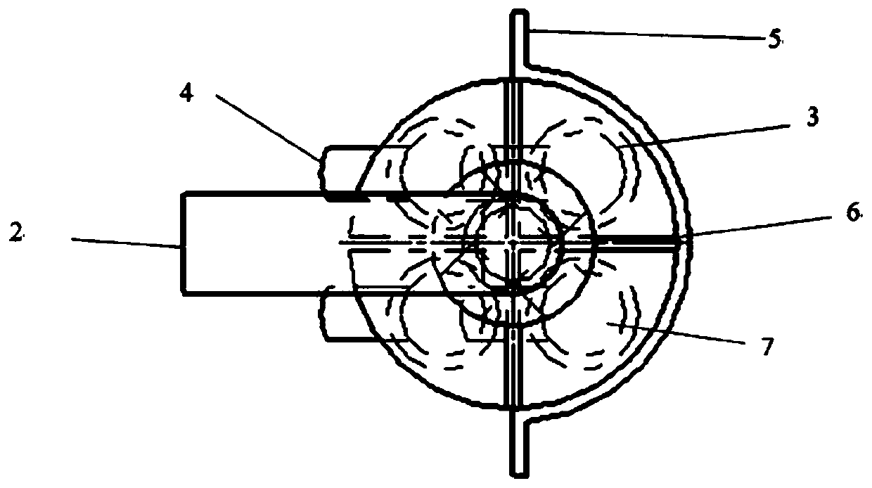
[0038] Such as Figure 6-7 As shown, the remover partition 6 is divided into upper and lower parts, the upper part is well-shaped, and the lower part is cross-shaped. This remover partition 6 divides the spray gun branch pipe 7 into four.
Embodiment 2
[0040] Such as Figure 8-9 As shown, the remover partition 6 is divided into upper and lower parts, the upper part is in the shape of a well, and the lower part is in the shape of a herringbone. This remover partition 6 divides the spray gun branch pipe 7 into three.
Embodiment 3
[0042] Figure 10-11 As shown, the stripper partition 6 is divided into upper and lower parts, and the upper and lower parts are in the shape of a well. This stripper partition 6 divides the spray gun branch pipe 7 into 5.
[0043] The foregoing embodiments reflect that the present invention can flexibly change the shape of the stripping agent partition plate 6 to ensure that it can evenly introduce the stripping agent into the spray gun branch pipe 7 of the stripping agent spray gun 3 with different lengths below, further ensuring that the spraying agent Uniformity of output.
[0044] Such as Figure 12 and Figure 13 ,Compared Figure 9 In the ordinary remover spray gun 3 without remover deflector 6 and without variable diameter, the left side of the ejected remover is less than the right side, and the middle part does not form a turbulent flow zone, which proves that the diffusion does not Perfect, small area, and the follow-up diffusion distribution effect is much diff...
PUM
Property
Measurement
Unit
Diameter
aaaaa
aaaaa
Abstract
The invention provides a flange type inlet pollutant solid remover spraying device. The flange type inlet pollutant solid remover spraying device comprises a remover inlet, a remover spray gun, a remover outlet, a remover guide plate and remover uniform-spacing plates, wherein the remover inlet and the remover outlet are formed in the remover spray gun; the remover spray gun is provided with a plurality of spray tubes; the remover guide plate is welded on the spray gun through a bracket, and is longitudinally arranged along the spray gun, and the cross section of the remover guide plate is Omega-shaped; moreover, the flat wing surface extended from the remover guide plate can increase the area of the remover guide plate, so that the remover can completely cover each circulating surface ina flue, and therefore, the remover is guaranteed to uniformly spread, and concentration distribution is reasonable; the remover uniform-spacing plates are arranged below an inlet bent tube, and a remover flowing in through the bent tube is uniformly distributed into each spray tube, so that pollutants in the smoke gas are guaranteed to be sufficiently in contact with the remover, and therefore, removal of the pollutants is guaranteed to reach the ideal degree. Besides, the pollutant solid remover spraying device has the advantages of being easy in replacing and convenient in maintaining and repairing.
Description
technical field [0001] The invention relates to the technical field of flue gas pollutant removal, in particular to a branch pipe pollutant solid removal agent injection device. Background technique [0002] There are many kinds of pollutants in the flue gas emitted by modern industries. The flue gas emitted by industries such as coal-fired power generation, waste incineration, metal smelting, cement production, and steel sintering mainly includes SO 2 , SO 3 , NO x , HCl, heavy metals (represented by mercury), dioxins and other pollutants. Among them, the acid gas SO 2 , NO x , SO 3 , HCl, etc. are the main pollutants in modern industrial flue gas, among which SO 2 , NO x The most common, if this kind of acid gas is not properly controlled, it will cause serious environmental pollution, such as acid rain, photochemical pollution, etc.; SO 3 As a pollutant that exists less in flue gas, its harm is higher than that of SO 2 more serious. Excessive SO in flue gas 3 I...
Claims
Application Information
Patent Timeline
Application Date:The date an application was filed.
Publication Date:The date a patent or application was officially published.
First Publication Date:The earliest publication date of a patent with the same application number.
Issue Date:Publication date of the patent grant document.
PCT Entry Date:The Entry date of PCT National Phase.
Estimated Expiry Date:The statutory expiry date of a patent right according to the Patent Law, and it is the longest term of protection that the patent right can achieve without the termination of the patent right due to other reasons(Term extension factor has been taken into account ).
Invalid Date:Actual expiry date is based on effective date or publication date of legal transaction data of invalid patent.