Rigid-flexible coupling clamping device

A rigid-flexible coupling, gripper technology, applied in the direction of chucks, manufacturing tools, manipulators, etc., can solve the problems of unfavorable industrial applications, fragile objects, and high costs, to enhance versatility and practicability, and increase load capacity. , the effect of reducing friction

Active Publication Date: 2019-12-13
FOSHAN UNIVERSITY
View PDF6 Cites 5 Cited by
  • Summary
  • Abstract
  • Description
  • Claims
  • Application Information

AI Technical Summary

Problems solved by technology

[0004] (1) Poor versatility of rigid grippers will lead to frequent replacement of different types of grippers to adapt to grippers of different sizes and shapes, which is not conducive to economy
[0005] (2) The high manufacturing cost of rigid grippers leads to high costs in the production and processing industries that rely on robots, which is not conducive to industrial applications
[0006] (3) Insufficient flexibility of the rigid gripper causes the rigid gripper to be easily damaged, which not only damages the object, affects the quality of the object's production and processing, but also affects the safety of production and processing
[0007] At this stage, there are also some flexible grippers on the market. Compared with rigid grippers, although the manufacturing cost of soft grippers is low, and they are integrally formed without assembly, the load capacity of soft grippers will be lower. Limited by some applications and scope of application, it cannot be widely used

Method used


Image

  • Rigid-flexible coupling clamping device
  • Rigid-flexible coupling clamping device
  • Rigid-flexible coupling clamping device

Examples


Embodiment

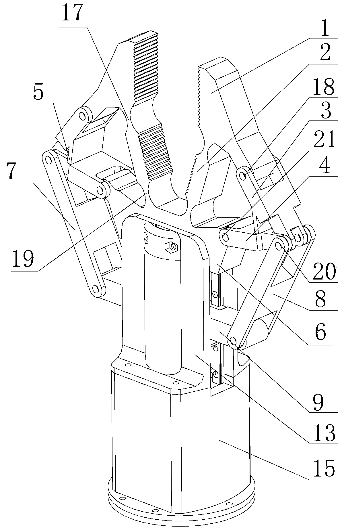
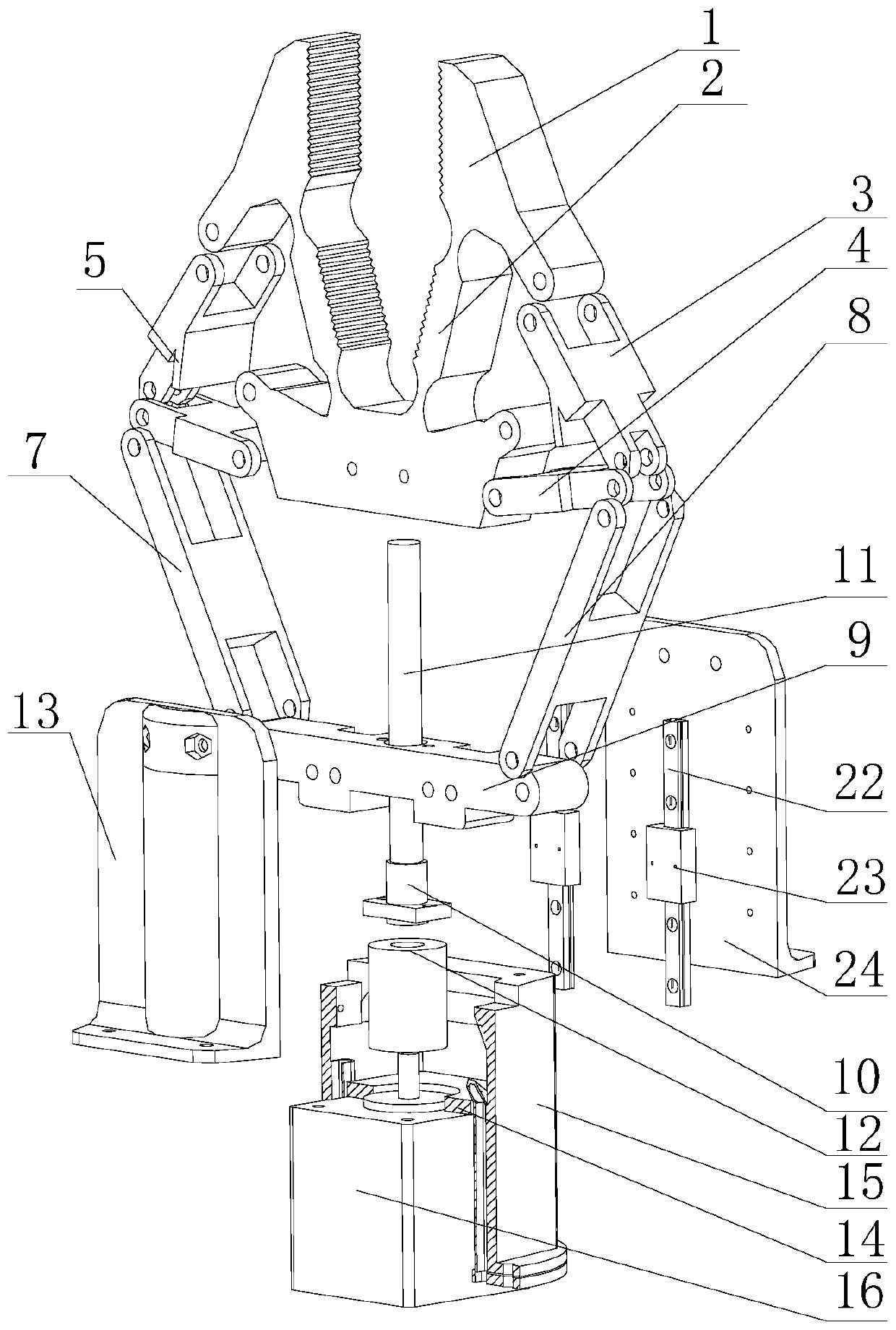
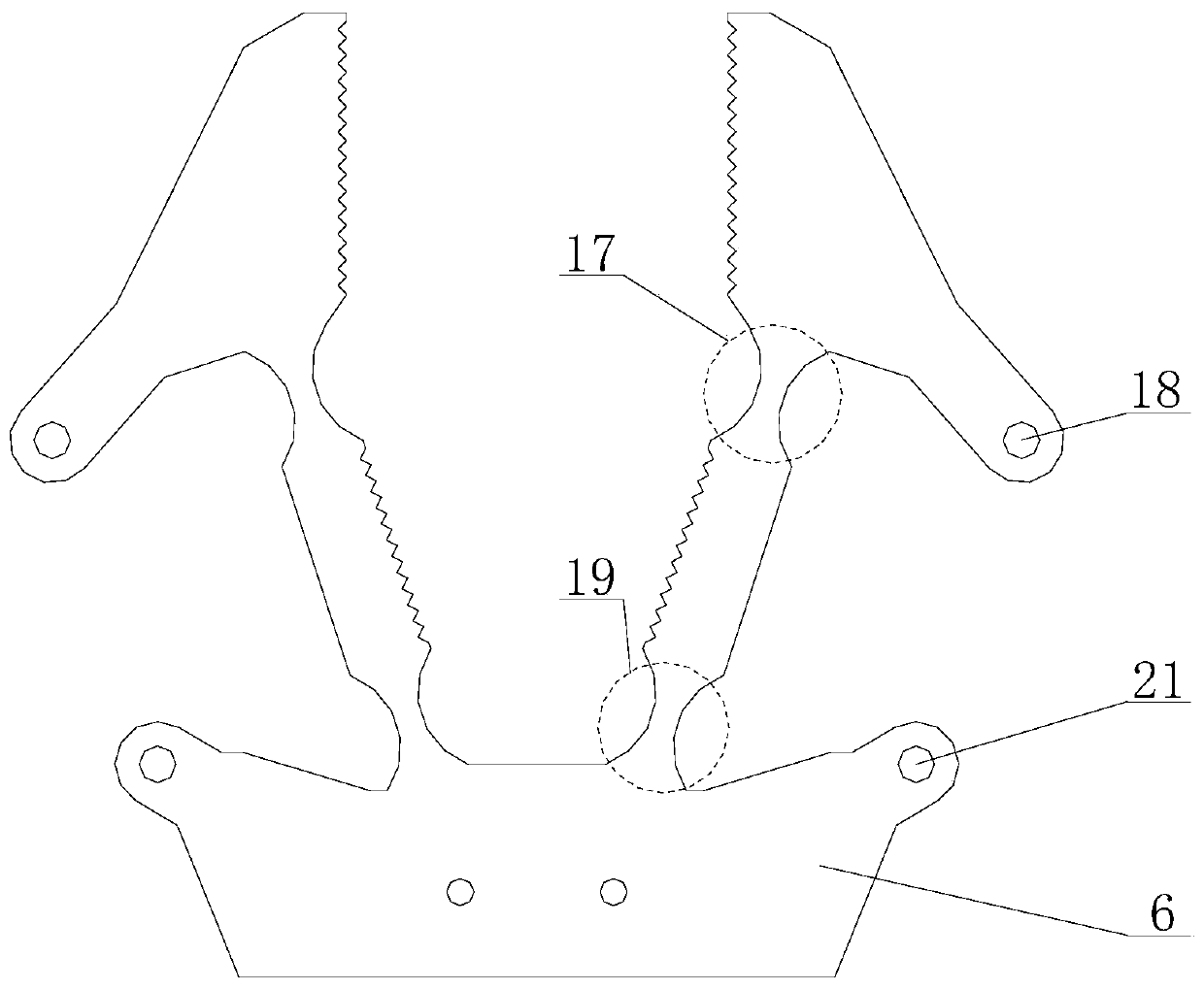
[0034] Such as Figure 1 to Figure 5 As shown, the rigid-flexible coupling clamper of the present invention includes a clamping mechanism and a driving mechanism, wherein the clamping mechanism includes two clamping parts arranged in a symmetrical mirror image, and a fixed part 6 connected to the two clamping parts, Both clamping parts include a flexible clamping rod one 2 and a flexible clamping rod two 1, the flexible clamping rod one 2 is used as the lower clamping part of the clamping part, and the flexible clamping rod two 1 is used as the upper clamping part of the clamping part The holder realizes the flexible clamping of the clamping object 25. One end of the flexible clamping rod one 2 is connected to the fixing part 6 , and the other end is connected to the flexible clamping rod two 1 . The clamping portion also includes a rigid clamping rod 3 and a rigid clamping drive rod 4 for increasing the load capacity of the clamp, the rigid clamping rod 3 is hinged with the ...


PUM


Abstract

The invention provides a rigid-flexible coupling clamping device. A clamping mechanism comprises two clamping parts and a fixing part which is connected with the two clamping parts. The two clamping parts each comprise a first flexible clamping rod and a second flexible clamping rod. One end of each first flexible clamping rod is connected with the fixing part, and the other end of each first flexible clamping rod is connected with the corresponding second flexible clamping rod. Each clamping part further comprises a rigid clamping rod and a rigid clamping driving rod, wherein each rigid clamping rod and each rigid clamping driving rod are used for increasing the load bearing capacity of the clamping device, and the rigid clamping rods are hinged to the second flexible clamping rods. The two ends of each rigid clamping driving rod are hinged to the corresponding rigid clamping rod and the fixing part. A driving mechanism is hinged to the rigid clamping driving rods of the two clampingparts, so that the rigid clamping rods are driven to move by driving the rigid clamping driving rods, and the power is transmitted to the first flexible clamping rods and the second flexible clampingrods, so that clamping or unfolding movement of the two clamping parts is achieved. The rigid-flexible coupling clamping device has the beneficial effects that the clamping flexibility and the load bearing capacity can be considered at the same time, so that the universality and the practicability of the clamping device are greatly enhanced, and the clamping device can be suitable for various application occasions.

Description

technical field [0001] The invention relates to the technical field of clamps, and more specifically, to a rigid-flexible coupling clamp. Background technique [0002] Robot technology is one of the important trends in the current technological development. Robots replace manual work to rely on robot grippers. Robot grippers are widely used in manufacturing and processing, material transportation, and picking and sorting tasks in daily life. [0003] At present, most of the widely used robot grippers are rigid grippers, and rigid grippers have problems such as poor versatility, high manufacturing costs, and insufficient flexibility. The specific performance is as follows: [0004] (1) The poor versatility of the rigid holder will lead to frequent replacement of different types of holders to adapt to holders of different sizes and shapes, which is not conducive to economy. [0005] (2) The high manufacturing cost of the rigid gripper leads to high cost in the production ind...

Claims


Application Information

Patent Timeline
Patent Type & Authority Applications(China)
IPC IPC(8): B25J15/08B25J15/12
CPCB25J15/08B25J15/12
Inventor 卢清华黄铭贤冯梓鸿陈为林
Owner FOSHAN UNIVERSITY
Why Eureka
Try Eureka