
A kind of compound shot-peening strengthening method for gear division and spiral bevel gear

A spiral bevel gear and shot peening technology, which is applied in the field of spiral bevel gear and gear partition composite shot peening, can solve the problem of tooth surface fatigue resistance, wear resistance, waste of manpower and material resources, and inconsistent gear surface performance and other problems, to achieve the effect of good wear resistance and fatigue resistance, strong wear resistance and fatigue resistance, and shorten the shot peening time

Active Publication Date: 2021-08-17
CENT SOUTH UNIV
View PDF0 Cites 0 Cited by
  • Summary
  • Abstract
  • Description
  • Claims
  • Application Information

AI Technical Summary

Problems solved by technology

The traditional shot peening is full tooth surface shot peening. On the one hand, there are problems of waste of manpower and material resources. On the other hand, due to the large spray surface, it is easy to cause uneven stress distribution, and the problem of overspray and underspray occurs. The force of each place is different. The traditional shot peening makes the actual force of the tooth surface not correspond to each place, that is, the surface performance of the gear cannot be consistent, which will easily lead to the problem of crack initiation, which will further affect the fatigue resistance of the tooth surface. , The improvement of wear resistance has an impact
Secondly, the traditional shot peening method has limited improvement in the mechanical properties of gears such as residual compressive stress, hardness, bending fatigue strength and contact fatigue strength.

Method used


Image

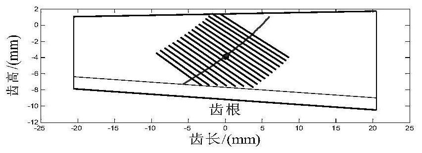
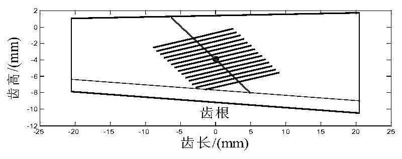
  • A kind of compound shot-peening strengthening method for gear division and spiral bevel gear
  • A kind of compound shot-peening strengthening method for gear division and spiral bevel gear
  • A kind of compound shot-peening strengthening method for gear division and spiral bevel gear

Examples


Embodiment Construction

[0024] Next, the technical solutions in the embodiments of the present invention will be apparent from the embodiment of the present invention, and it is clearly described, and it is understood that the described embodiments are merely embodiments of the present invention, not all of the embodiments. Based on the embodiments of the present invention, those of ordinary skill in the art will belong to the scope of the present invention without all other embodiments obtained without creative labor.

[0025] In this embodiment, the coil gear sub-gear is used in the heavy-duty vehicle installed bicycle, considering the high contact stress of the gear, and since the high axial load of the small wheel is large, it is easy to slip. Creating edge and tubing contact, resulting in problems with short wear, in particular reversing surface), short fatigue life, intended to work with the vehicle with the vehicle with the vehicle with the vehicle with the same life, according to the gear and the...


PUM

PropertyMeasurementUnit
diameteraaaaaaaaaa

Abstract

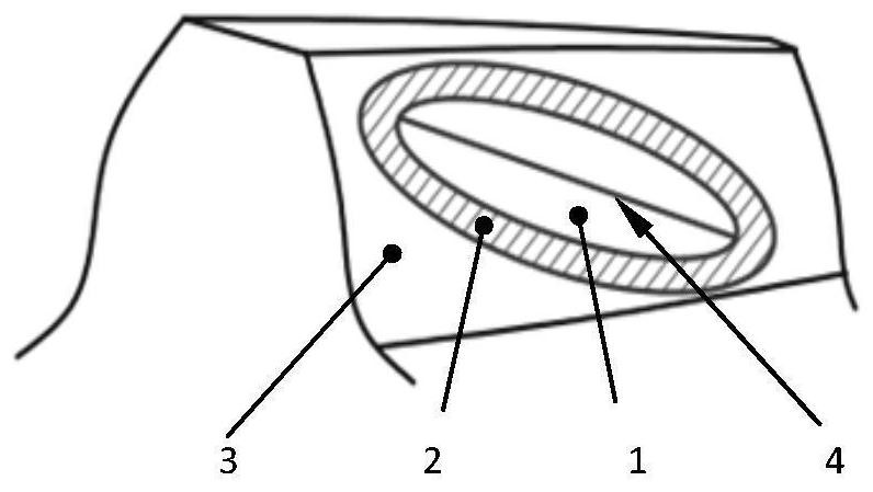
The invention provides a method for compound shot-peening strengthening of gear partitions, which includes the following steps: analyzing the meshing characteristics of gear tooth surfaces; dividing the gear tooth surfaces into shot-peening areas, transition areas and non-shot-peening areas according to the analysis results of meshing contact stress; Among them, the shot peening area corresponds to the tooth surface meshing area of ​​the gear, the transition area corresponds to the area where the gear tooth surface is located outside the shot peening area and the contact stress is not zero, and the non-peening area corresponds to the area where the gear tooth surface is located outside the transition area; The shot peening area and the transition area are shot peened to ensure that the residual compressive stress in the shot peening area is greater than the residual compressive stress in the transition area. This method can effectively improve the anti-fatigue and wear resistance of the spiral bevel gear, reduce the noise level of the gear pair, and achieve the goal of consistency between the axle spiral bevel gear and the vehicle life.

Description

Technical field [0001] The present invention belongs to the field of gear surface reinforcement technology, and it is related to a gear partition composite shot mutation method and a spiral cone gear. Background technique [0002] Spraying reinforcement technology is a metal surface cold processing technology, and gear makers typically use such a process as a process such as increasing gear anti-fatigue strength. At present, the surface strengthening of the bridge spiral cone gear is mainly conventionally induced, mainly for centrifugal shotmia. Traditional shot blasting is a total of human and labor waste, on the one hand, on the other hand, due to the large discharge, it is easy to cause uneven stress distribution, and there is a problem of spray and undressing, and gear tooth surface The stress size of each department is different. It uses traditional sprayers to make the actual status of the tooth surface do not correspond, that is, the surface performance of the gear cannot ...

Claims


Application Information

Patent Timeline
Patent Type & Authority Patents(China)
IPC IPC(8): C21D7/06
CPCC21D7/06
Inventor 严宏志朱鹏飞陈志吴顺兴伊伟彬
Owner CENT SOUTH UNIV
Learn More