Water pump speed regulating mechanism capable of achieving temperature control over flow

An automatic temperature control and speed regulating mechanism technology, which is applied in the control of coolant flow, engine components, machines/engines, etc., can solve the problems of large flow loss, small adjustment range, and fast flow speed, and achieve accurate control of return water temperature , high speed control precision, precise speed adjustment effect

Active Publication Date: 2019-12-13
WEICHAI HEAVY MACHINERY
View PDF5 Cites 2 Cited by
  • Summary
  • Abstract
  • Description
  • Claims
  • Application Information

AI Technical Summary

Problems solved by technology

[0005] (1) The transmission ratio of the water pump cannot be adjusted, so that the driving power of the water pump cannot be reduced;
[0006] (2) The water pump flow is controlled through the thermostat switch, and the adjustment range is small;
[0007] (3) When the engine starts running, the flow area at the temperature control point is small, the flow velocity is fast, and the flow loss is large;
[0008] (4) Negative pressure is formed at the water inlet of the water pump, and blisters may be precipitated, causing cavitation

Method used


Image

  • Water pump speed regulating mechanism capable of achieving temperature control over flow
  • Water pump speed regulating mechanism capable of achieving temperature control over flow
  • Water pump speed regulating mechanism capable of achieving temperature control over flow

Examples


Embodiment 1

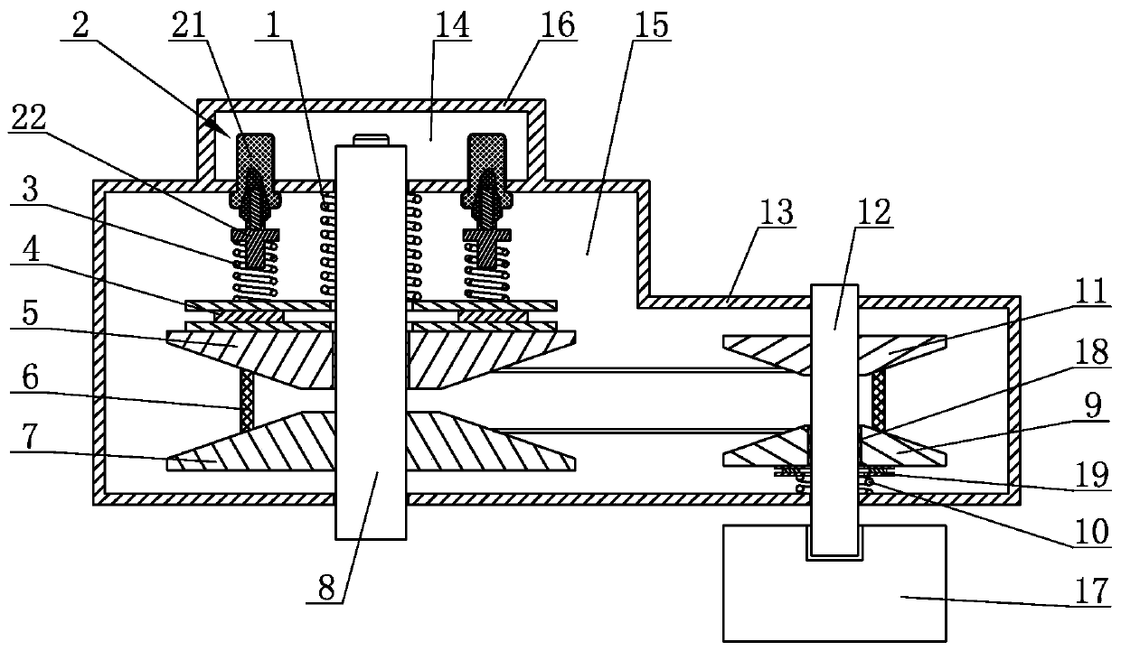
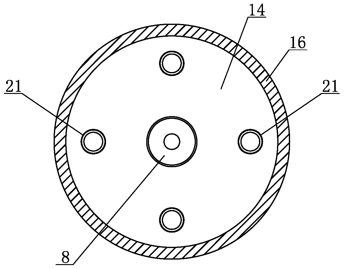
[0035] Such as figure 1 As shown, a water pump speed regulating mechanism with automatic temperature control flow includes: the execution chamber 15 surrounded by the execution chamber casing 13 and the temperature control chamber 14 surrounded by the temperature control chamber casing 16, the execution chamber casing 13 It is fixedly connected with the temperature control chamber housing 16, the temperature control chamber 14 is located on one side of the execution chamber 15, the temperature control chamber 14 is connected with the return water before the engine thermostat, and the water inlet of the temperature control chamber 14 is set in the temperature control chamber The housing 16 , or the driving shaft 8 is hollowly provided with a water inlet channel, and the water inlet channel communicates with the temperature control chamber 14 .

[0036] The execution room 15 is provided with a variable speed actuator, the variable speed actuator is a belt transmission mechanism ...

Embodiment 2

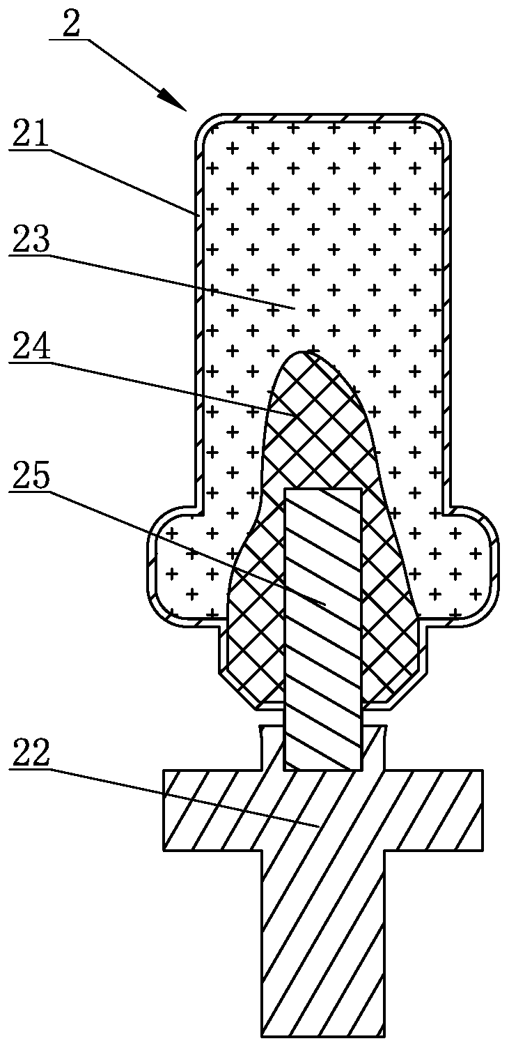
[0053] The structure of the second embodiment is basically the same as that of the first embodiment, the only difference is that the temperature control actuator 2 is arranged on one side of the driven moving cone 9, and a The active adjustment spring is not shown in detail here.


PUM


Abstract

The invention discloses a water pump speed regulating mechanism capable of achieving temperature control over flow. The water pump speed regulating mechanism comprises a temperature control chamber and an executing chamber. The temperature control chamber is provided with a temperature executing mechanism. The temperature control chamber is provided with a water inlet, and the executing chamber isprovided with a variable speed executing mechanism. The variable speed executing mechanism is provided with a drive shaft and a driven shaft stretching out of the executing chamber. The drive shaft is a power input shaft, and the driven shaft is a power output shaft. The temperature control executing mechanism stretches into the executing chamber and is connected with the variable speed executingmechanism. The temperature control executing mechanism adjusts the transmission ratio of the variable speed executing mechanism according to the water temperature of the temperature control chamber.When the water return temperature of an engine is low, under the adjustment of the temperature control executing mechanism, the transmission ratio of the variable speed executing mechanism becomes small, flow of a water pump is reduced, the temperature of the engine is increased rapidly, and the water pump can meet different work conditions of the engine.

Description

technical field [0001] The invention relates to the technical field of engines, in particular to a water pump speed regulating mechanism with automatic temperature control flow. Background technique [0002] At present, when the engine for power generation is warming up, the oil temperature and water temperature are too low, but the water pump is still working at full capacity, and a large amount of circulating water circulates ineffectively in the engine, which not only wastes the warm-up time for the engine to work from normal temperature to a suitable temperature, but also cause energy waste. Furthermore, under low working conditions of the generator type, the water pump works at full load and the circulating water flow is large, resulting in low engine oil temperature, increased engine oil consumption and fuel consumption, increased wear of cylinder liners and piston rings, and increased risk of cylinder scuffing. [0003] In order to solve the above-mentioned documents...

Claims


Application Information

Patent Timeline
Patent Type & Authority Applications(China)
IPC IPC(8): F01P7/16F04B49/20
CPCF01P7/164F04B49/20
Inventor 马宝光李玉森王浩
Owner WEICHAI HEAVY MACHINERY
Why Eureka
Try Eureka