Electro-hydraulic servo pressure infiltration device

An electro-hydraulic servo and platen technology, which can be used in measurement devices, permeability/surface area analysis, suspension and porous material analysis, etc. To achieve the effect of simple structure, guaranteed stability and convenient use

Active Publication Date: 2019-12-13
YANTAI ZHONGYU AEROHYDRAULIC
View PDF10 Cites 3 Cited by
  • Summary
  • Abstract
  • Description
  • Claims
  • Application Information

AI Technical Summary

Problems solved by technology

[0005] The purpose of the present invention is to solve the shortcomings in the prior art that the cylinder in the piezo-osmosis device is inconvenient to adjust the height, and it is not convenient to clamp the cylinder, and the cylinder is not fixed firmly. A proposed electro-hydraulic servo piezo-osmotic device

Method used


Image

  • Electro-hydraulic servo pressure infiltration device
  • Electro-hydraulic servo pressure infiltration device
  • Electro-hydraulic servo pressure infiltration device

Examples


Embodiment 1

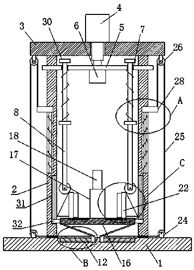
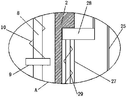
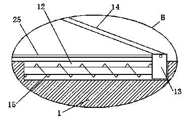
[0029] refer to Figure 1-5 , an electro-hydraulic servo pressure seepage device, comprising a workbench 1, two support plates 2 are fixedly installed on the top of the workbench 1, a top plate 3 is fixedly installed on the top of the two support plates 2, and a hydraulic pressure is fixedly installed on the top of the top plate 3 Cylinder 4, the piston rod of hydraulic cylinder 4 extends to the bottom of the top plate 3 and is fixedly installed with a pressure plate 5, the bottom of the pressure plate 5 is provided with a pressure plate 6, and the top of the workbench 1 is provided with two transmission grooves 12, two transmission grooves 12 The transmission block 13 is slidingly installed inside, the top of the transmission block 13 extends to the top of the workbench 1, and the transmission rod 14 is installed on the transmission block 13, and the same lifting plate 16 is installed on the top of the two transmission rods 14. A cylinder 17 is provided on the top of the lift...

Embodiment 2

[0040] refer to Figure 1-5 , an electro-hydraulic servo piezo-infiltration device, comprising a workbench 1, two support plates 2 are fixedly installed on the top of the workbench 1 by welding, and a top plate 3 is fixedly installed on the top of the two support plates 2 by welding, and the top of the top plate 3 A hydraulic cylinder 4 is fixedly installed by welding. The piston rod of the hydraulic cylinder 4 extends to the bottom of the top plate 3 and a pressure plate 5 is fixedly installed by welding. Slot 12, two drive slots 12 are slidingly installed with transmission block 13, the top of transmission block 13 extends to the top of workbench 1, and transmission rod 14 is installed on the transmission block 13, and the top of two transmission rods 14 rotates The same lifting plate 16 is installed, the top of the lifting plate 16 is provided with a cylinder 17, the cylinder 17 is provided with a percolation chamber, the top of the cylinder 17 is provided with a plunger 18...


PUM


Abstract

The invention belongs to the technical field of pressure infiltration devices, especially relates to an electro-hydraulic servo pressure infiltration device, and aims at solving the problems that a cylinder in the pressure infiltration device is inconvenient to adjust the height and clamp and is not fixed firmly. The device comprises a workbench, two supporting plates are fixedly mounted at the top of the workbench, a top plate is fixedly mounted at the tops of the two supporting plates, a hydraulic cylinder is fixedly mounted at the top of the top plate, and a piston rod of the hydraulic cylinder extends to position under the top plate and is fixedly provided with a pressing plate. The device has the advantages that the structure is simple, use is convenient, the use height of the cylinder can be adjusted, the cylinder can be clamped, and the stability of the cylinder in the experiment process is ensured.

Description

technical field [0001] The invention relates to the technical field of piezo-osmosis devices, in particular to an electro-hydraulic servo piezo-osmosis device. Background technique [0002] At present, many of the processing materials in the petroleum, chemical, mining, pharmaceutical, food and other industrial fields are granular or porous media materials. The research on the piezo-osmotic characteristics of such materials is the basis for their processing and application. Usually, the physical characteristics of the material will change greatly during the pressure infiltration process. Under the action of pressure, the sparse granular material will first produce elastoplastic deformation, eliminate a large number of gaps between the particles, and become a dense granular material. Granules, as the pressure increases, the particles are broken, and the oil seeps out to form a liquid-solid coupling body. [0003] After retrieval, the patent document with application number 2...

Claims


Application Information

Patent Timeline
IPC IPC(8): G01N15/08
CPCG01N15/0826G01N15/0806
Inventor 倪宇佩李祥至
Owner YANTAI ZHONGYU AEROHYDRAULIC
Why Eureka
Try Eureka