Mould detection device and detection method

A detection device and mold technology, applied in the field of optical detection, can solve the problems of poor measurement, large overall equipment, weak strength, etc., and achieve the effects of flexible design scheme, improved detection efficiency, and improved accuracy

Inactive Publication Date: 2019-12-13
长春长光东方光电技术有限公司
View PDF15 Cites 6 Cited by
  • Summary
  • Abstract
  • Description
  • Claims
  • Application Information

AI Technical Summary

Problems solved by technology

The existing methods for detecting Aspergillus flavus using ultraviolet light mostly use the reflected light at a specific angle on the surface of the sample to be tested, which can only detect the mildew at a certain position of the sample to be tested, and the accuracy of the test results is low. To detect mildew on the surface of the sample, multiple ultraviolet detection sub-modules and multiple spectral receiving devices are required. The received multiple spectral images are analyzed, and the data processing process is complicated, which greatly reduces the detection efficiency. If the sample to be tested is detected by scattered light, this problem can be avoided.
There is no detection scheme using scattered light in the prior art, because the scattered light diverges in all directions, the intensity is weak, and it is difficult to measure

Method used


Image

  • Mould detection device and detection method
  • Mould detection device and detection method

Examples


Embodiment 1

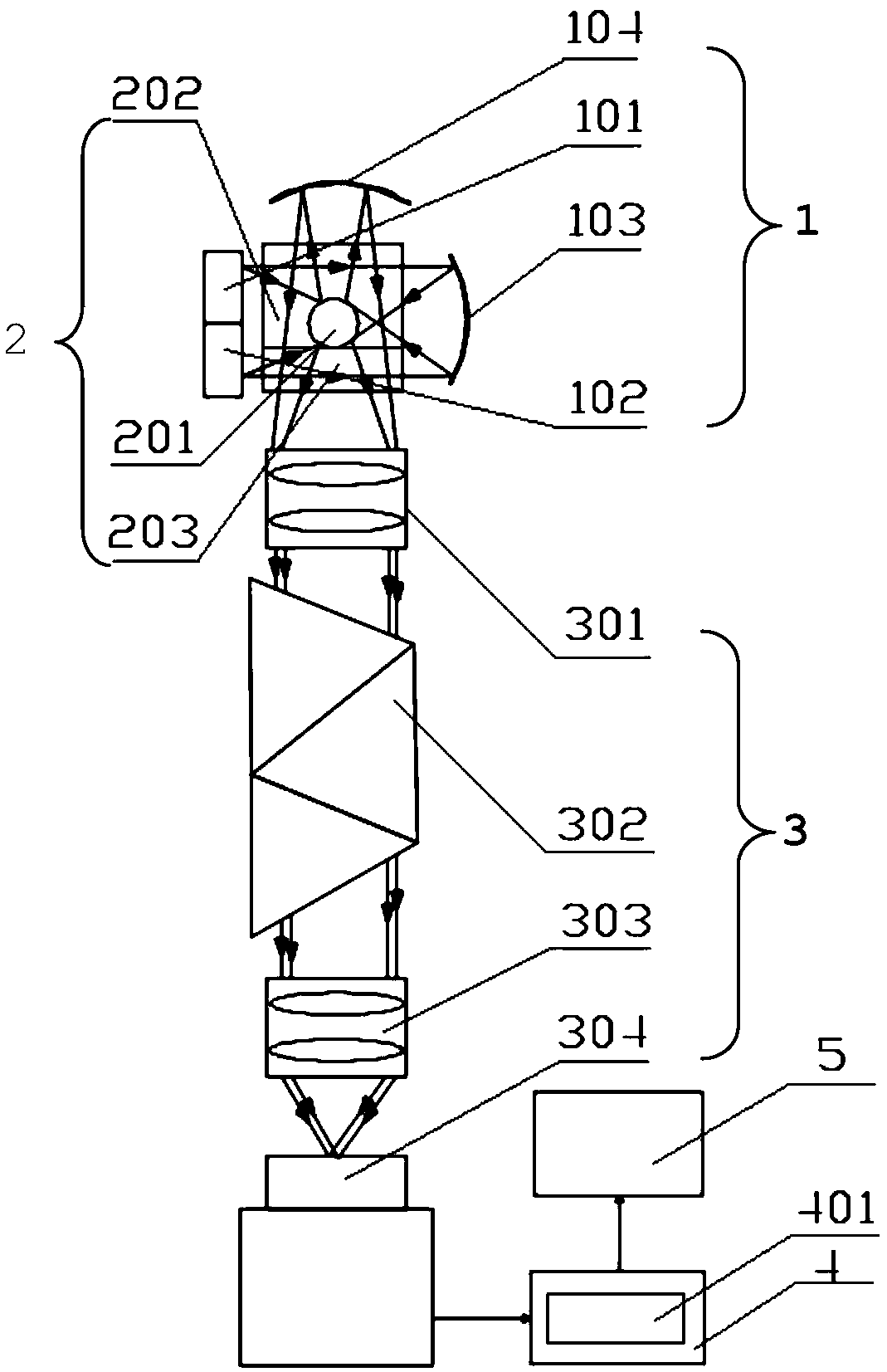
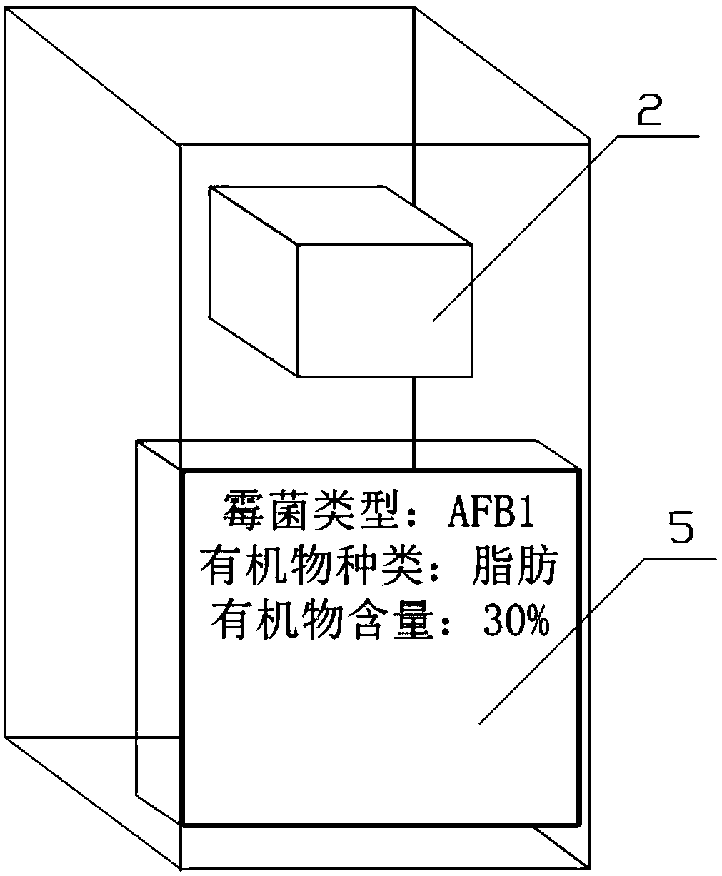
[0036] Example 1: Combining figure 1 and figure 2 Describe this embodiment, the optical structure of a kind of mold detection device of this embodiment is as follows figure 1 As shown, it includes: a detection module 1 , a sample chamber 2 , a detection module 3 and a data processing module 4 .

[0037] The detection module 1 includes an infrared detection sub-module 101, an ultraviolet detection sub-module 102, a first mirror 103 and a second mirror 104, and the infrared detection sub-module 101 is used to emit incident infrared light to excite the The organic matter in the sample 201 emits a specific spectrum, and the ultraviolet detection submodule 102 is used to emit incident ultraviolet light to excite the mold on the surface of the sample 201 to be tested to emit a specific spectrum, and the first reflector 103 is arranged at the incident On the propagation path of the infrared light and the incident ultraviolet light, it is used to change the propagation direction of...

Embodiment 2

[0046] Embodiment 2: A mold detection device of this embodiment is further defined on the basis of the specific embodiment 1. The focus position of the first reflector 103 coincides with the geometric center of the sample 201 to be tested during detection. The effect of such settings It is capable of reflecting and converging all the light emitted by the light source to the surface of the sample 201 to be tested, so as to ensure sufficient illumination.

Embodiment 3

[0047] Embodiment 3: A kind of mold detection device of this embodiment is further defined on the basis of specific embodiment 1. The focus position of the second reflector 104 coincides with the geometric center of the sample to be tested 201 during detection, so that the sample to be tested After being reflected by the second reflector 104, the scattered light at 201 can enter the subsequent optical module at a smaller angle.


PUM


Abstract

The invention relates to the technical field of optical detection, in particular to a mould detection device and a detection method thereof. Aiming at the problems that in the prior art, reflected light on the surface of a sample to be detected is mainly used for detection, only the mildew condition of a certain position of the sample to be detected can be detected, and the accuracy of a detectionresult is low, an incident light angle is changed by using a first reflector, and scattered light on the surface of the sample to be detected is collected by using a second reflector, so that the comprehensive detection accuracy of the surface of the sample to be detected is greatly improved, and the mould detection device and the detection method thereof can be applied to the fields of quality detection of agricultural products or food and the like.

Description

technical field [0001] The invention relates to the technical field of optical detection, in particular to a mold detection device and detection method. Background technique [0002] Mycotoxins such as aflatoxin, hertoxin, T2 toxin, and deoxynivalenol have strong carcinogenic, teratogenic and mutagenic effects, among which aflatoxin B1 (AFB1) is the most toxic. Human consumption of food contaminated by aflatoxin can induce primary liver cancer, gastric cancer, lung cancer, and may also cause malformation of embryonic organs. At present, studies at home and abroad have found that aflatoxin pollution is mainly distributed in various stages of crop growth, receiving, transportation and product processing, covering a wide range and seriously affecting the health of humans, livestock and poultry. A large number of studies have been carried out on fungal detection, especially aflatoxin detection, in the world. [0003] At present, liquid chromatography is mainly used for the det...

Claims


Application Information

Patent Timeline
Patent Type & Authority Applications(China)
IPC IPC(8): G01N21/33G01N21/3563G01N21/3577G01N21/359
CPCG01N21/33G01N21/3563G01N21/3577G01N21/359
Inventor 孙强王健曲锋韩希珍
Owner 长春长光东方光电技术有限公司
Why Eureka
Try Eureka